PLC digital input interface is not complicated, we all know PLC in order to improve anti-jamming capability, the input interface uses optocouplers to isolate the input signal and internal processing circuit transmission. Therefore, the input signal only drives the internal LED of the optocoupler to be turned on and is received by the optocoupler of the optocoupler, so that the external input signal can be reliably transmitted.
At present, PLC digital input ports are generally divided into single-end common-end and double-end inputs. Each manufacturer's single-end common point (Com) interface has photoelectric coupler positive and negative common point, Japanese PLC usually adopts positive common point , European PLC is accustomed to using the negative common point; Japanese PLC supply European market is also used in Europe according to the common use of negative polarity; in order to be flexible to use and developed a single-ended common point (S/S) optional type, according to need single-end common point Can be connected to the negative electrode can also be connected to the positive electrode.
Because of these differences, the user needs a certain distinction and understanding when selecting an external sensor to use the sensor and PLC correctly to lay the foundation for the later programming work and system stability.
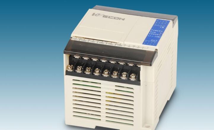
The proximity switch is a position switch that can operate without mechanical contact with the moving part. When the object approaches the sensing surface of the switch to the action distance, the switch can be actuated without mechanical contact and exerting any pressure, thereby driving the DC electric apparatus. Or provide control instructions to a plc device. Proximity switch is a kind of switch type sensor (namely non-contact switch). It has both the characteristics of limit switch and micro switch, and it has the sensing performance, reliable operation, stable performance, fast frequency response, long service life, and anti-interference. Strong ability, and with waterproof, shockproof, corrosion-resistant and other characteristics. Products are inductive, capacitive, Hall, AC, DC type.
Proximity switch, also known as non-contact proximity switch, is an ideal electronic switch sensor. When the metal detector is close to the sensing area of ​​the switch, the switch can be contactless, no pressure, no spark, quickly send electrical instructions, accurately reflect the position and stroke of the moving mechanism, even if used for general stroke control, positioning accuracy, operation The frequency, the service life, the convenience of installation and adjustment, and the applicability to harsh environments cannot be compared with the general mechanical type of travel switch. It is widely used in machine tools, metallurgy, chemical, textile and printing industries. In the automatic control system can be used as limit, counting, positioning control and automatic protection links.
The proximity switch can be classified into a cylinder type, a square type, a groove type, a perforated (through) type, and a separate type according to its outer shape. Cylindrical type is easy to install, but its detection characteristics are the same. The groove type detection part is inside the tank. It is used to detect the objects passing through the tank. The penetration type is rarely produced in our country, while in Japan it is more common and can be used. Small parts such as small screws or balls and buoys are assembled into water level detection devices.
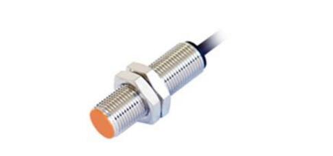
Since the input of plc is divided into two types of NPN input and PNP input, the proximity switch is also divided into two types of NPN and PNP. Only when the proximity switch type and PLC input type are consistent, when there is an object approaching PLC will have input signal. Generally, the proximity switches of Japan and South Korea are NPN types by default, and the proximity switches of Europe and the United States are PNP types by default. Proximity switches are different from PLCs. Both Japanese and Korean systems and European and American systems have NPN and PNP types for each proximity switch. . PLC can't have NPN type and PNP type, because the polarity of PLC can be changed through the wiring, and once the proximity switch is fixed, it can't be changed.
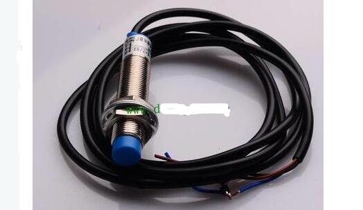
Figure 1 proximity switch
As shown in Figure 1, this is a common proximity switch. It is cylindrical. Generally, its diameter is thicker and the detection distance is longer.
According to different detection objects, the proximity switch is divided into two kinds of inductive and capacitive. The inductive proximity switch uses the Hall effect to detect the change of the magnetic field. Since the metal can cause the change of the magnetic field, the inductive proximity switch mainly detects the metal It is steel. A capacitive proximity switch is essentially a plate of a capacitor. When the object to be detected approaches, the dielectric constant of the entire capacitor changes, so that an object is considered to be close. Therefore, the capacitive proximity switch can detect metal and can also detect non- Metals, but generally we use inductive proximity switches to detect metals. Therefore, we all use capacitive proximity switches to detect non-metals. Such as ceramics, paper, wood and so on.
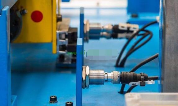
Figure 2 Field application of proximity switches
As shown in Figure 2, it is the practical application of the proximity switch in the industrial field. It is generally fixed by a bracket. When the detection object is close, its indicator light will be on, indicating that the proximity switch has an output. Similarly, if the wiring is correct, the PLC will There will be an input signal. How does the proximity switch access the PLC's input point? In fact, it is similar to the push button switch. Generally, the proximity switch has three wires, which are brown, blue and black. Brown and blue are power supplies, usually brown for 24V and blue for 0V. Black is the signal line that receives the PLC input and this signal is exactly what we need.
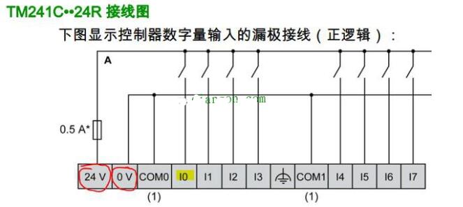
Figure 2 PLC hardware manual
As shown in Figure 2, this is the PLC's hardware manual. If we want to connect the signal of the proximity switch to the input point I0, which is the yellow highlighter part, what should we do? In fact, it is very simple, look at the red circle part, PLC has provided us with the output power, we only need to connect the three lines of the proximity switch.
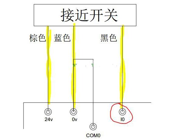
Figure 3 The actual wiring of the proximity switch
As shown in Figure 3, this is the actual wiring of the PLC. The yellow highlighter identifies the three wires of the proximity switch. Brown and blue are connected to the 24V and 0V of the PLC, and black is connected to the I0. When an object reaches the sensing distance of the proximity switch, the PLC's I0 will have an input and we can do it in the program. It should be noted that 0V and COM0 are shorted in the figure. Therefore, this connection method is suitable for PNP type proximity switches. The NPN-type proximity switch does not have any signal. The connection of the proximity switch is only relevant to NPN, PNP type and inductive capacitive.
Another point to note is that the proximity switch should be directly connected to the input of the PLC. Don't add any kind of relays and other conversion devices in the middle.
What is a fiber optic slip ring?
A fiber optic slip ring is a device that allows for the transfer of data, power, and signals between two rotating objects. The ring is made up of one or more optical fibers that are used to transmit light signals. These signals can be used to send power, data, or other signals between the two objects. The fiber optic slip ring is a newer technology that has many benefits over traditional slip rings.
How do fiber optic slip rings work?
A fiber optic slip ring is a device that allows electric current and optical signals to pass through a rotating joint. This is often used in applications where it is necessary to transfer data or power between two stationary points while the object rotates. The fiber optic slip ring uses light rather than metal to conduct these signals, which makes it ideal for use in high-speed or hazardous environments.
Types of fiber optic slip rings
When it comes to telecommunications, fiber optics are king. They're the backbone of almost every network today, and they're getting faster and more reliable all the time. That's thanks in part to a technology called fiber optic slip rings.
Advantages of fiber optic slip rings
A fiber optic slip ring is a device used in optical communication. It is a component of many fiber optic networks and it allows for the transmission of data over long distances without losing signal quality. Fiber optic slip rings are also used to improve the performance of other optical systems.
Disadvantages of fiber optic slip rings
Fiber optic slip rings are growing in popularity for rotating applications. Fiber optic slip rings provide many advantages over traditional electrical slip rings, including much smaller size, weight, and power consumption. However, fiber optic slip rings also have a few disadvantages. One disadvantage is that they can be more expensive than traditional electrical slip rings. Additionally, fiber optic cables are more fragile than electrical cables, so they can be more susceptible to damage.
Conclusion: What are the benefits and drawbacks of fiber optic slip rings?
When it comes to fiber optic slip rings, there are both benefits and drawbacks to consider. On the one hand, fiber optic slip rings offer a number of advantages over traditional metal contact slip rings. They are lighter in weight, which makes them easier to install and transport. They also generate less heat, making them safer to use in hazardous environments. Additionally, they provide superior performance in terms of electrical noise and signal integrity.
However, fiber optic slip rings also have some drawbacks. They are more expensive than traditional metal contact slip rings, and they can be more difficult to repair if they malfunction. Additionally, they may not be suitable for some applications due to their limited range of motion.
Fiber Optic Slip Ring,Brass Slip Ring,Fiber Optic Silp Ring,Electrical Rotary Joint
Dongguan Oubaibo Technology Co., Ltd. , https://www.sliprobs.com