In the process of low-voltage supply and distribution points, with the increase of the inductive load usage of motors, transformers, transformers, etc., the proportion of reactive power in the use of electric energy is increasing. Reactive power compensation is especially important. However, during the use of the reactive power compensation device, due to various errors such as wiring errors, improper current and voltage sampling position, current transformer installation position, improper installation position of the low voltage meter, etc., reactive power is not compensated. The reasons are generally the following.
1 Current transformer sampling error
Under normal circumstances, it should be as shown in Figure 1: However, in actual use, some people connect to Figure 2 or Figure 3 because they do not understand the working principle for wiring, installation or other reasons. In the wiring of Fig. 2, since the current of the capacitor cabinet is taken instead of the current signal of the entire power supply, the capacitor itself is compensated for the reactive power compensation instead of the power consumption. Therefore, it is bound to cause no compensation. In the wiring of Fig. 3, the sampling transformer and the sampling voltage are repeated, resulting in no phase relationship between the current and the voltage, resulting in a wrong display of the power factor, so that no compensation occurs.
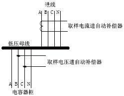
Figure 1 correct voltage and current sampling method
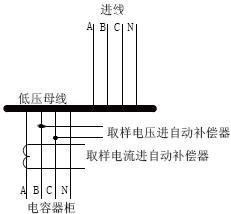
Figure 2 Wrong voltage and current sampling mode 1
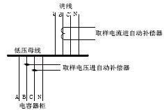
Figure 3 Wrong voltage and current sampling mode 2
In short: when the transformer is installed, the measured current and the measured voltage sample cannot be in phase. When the sampling current is phase A, the measured voltage should be taken as phase B and phase C. Current sampling should be taken from the main line side transformer and not the transformer entering the capacitor outlet side.
2 Contactor, indicator light working power source is selected incorrectly
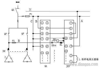
The author once found in the process of reactive power failure of a unit that the device user installed a reactive power compensation disk, the reactive power compensation indicator indicates normal, and the contactor is normal, but the reactive power compensation is not ideal. On-site inspection revealed that it was caused by the fuse fuse at the upper end of the contactor. The schematic diagram is shown in Figure 4. Reason analysis: Since the working power of the contactor coil KML and the contactor pull-in indicator HL is taken from under the knife switch, the contactor coil KML and the contactor suction indication are in the fuse fuse state. The working power of the lamp HL can still work normally, and the primary line of the capacitor is in the off state, resulting in reactive power compensation. However, the indicator light is normal, and the normal contact of the contactor creates an illusion of normal operation for the user. The reason is that due to the improper position of the reactive power compensation control power supply, although it can work under normal conditions, once the fault occurs in the primary line below the fuse, and the indicator light is normally indicated, an invisible hidden fault is caused. The user cannot be judged correctly. If the modification as shown in Fig. 5 is made, the fuse fuse FU on the primary line of the capacitor is changed into the miniature circuit breaker QF, and one end of the reactive power compensation control line is changed to the lower end of the miniature circuit breaker, and the contactor and the indication are changed after the modification. The control power of the lamp can effectively solve the above drawbacks at the lower end of the circuit breaker.
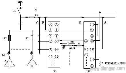
QK--knife switch KM--contactor C--capacitor FU--fuse fuse KM L - contactor coil KM NO - contactor normally open contact
HL--indicator QA--conversion switch JKW--reactive power automatic compensator A, B, C--phase line N-- center line
Figure 4: Reactive power compensation control circuit with improper voltage position
QK--knife switch KM--contactor C--capacitor FU--fuse fuse KM L - contactor coil KM NO - contactor normally open contact
HL--indicator QA--conversion switch JKW--reactive power automatic compensator A, B, C--phase line N--middle line QF--miniature circuit breaker
Figure 5: Reactive power compensation control line power supply position after correction
In short: the reactive power compensation indicator should be clear and true, and can correctly reflect the working state of the capacitor, so that the user can see the real operation of the reactive power compensation device at a glance.
3 reactive power compensation controller parameter settings are improper
3.1 Current ratio setting error
When the controller measures the current display abnormality or displays it as 000, it indicates that the current ratio is set incorrectly or the current transformer and the controller line are open or no load. The reactive current compensation controller parameter setting menu “Current Ratio†setting item should be checked, and its value must be the same as the ratio of the main incoming current transformer. For example, the main incoming line sampling current transformer ratio is 200/5, control The "Current Ratio" setting should be 40; when the sampling current transformer ratio is 400/5, the controller "Current Ratio" setting should be 80. If the current transformer and the controller current terminal line have an open circuit, check the processing.
3.2 Power factor parameter setting is too low or other
When the reactive power compensation effect is not good, the parameter setting item of the reactive power compensation controller should also be checked. The parameters related to the compensation accuracy have three parameters: “target cosφâ€, “threshold†and “capacitance valueâ€, which can improve the target “target cosφâ€. The value is reduced by the "threshold" setting value. The recommended setting target is cosφ=1.00, not lower than 0.85; the threshold is 1.0; each capacitor capacity setting is the same as the actual capacitor capacity. Due to the large difference in the capacity distribution of some design capacitors, it is recommended to use the capacitor coding method to adjust the capacitor capacity, which will achieve the desired compensation effect.
In short: the setting of the compensator must be reasonable and correct in the reactive power compensation, otherwise it will cause the reactive power to not compensate or the compensation effect is not good.
4 Metering point position selection error
The correct metering position during metering should be as shown in Figure 6. However, some errors are installed in the capacitor and below the contacts. As shown in Fig. 7, since the metering is installed below the capacitor once the circuit has been compensated but the power is compensated but not metered in, the reactive power before compensation is still available.
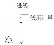
Figure 6 correct low pressure metering point
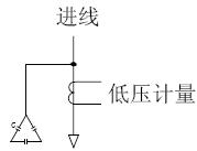
Figure 7 Wrong low pressure metering point
In the case of reactive power measurement, it is necessary to select the measurement position, otherwise it will cause unnecessary loss due to measurement inaccuracy.
5 Conclusion
In the reactive power compensation, there are often uncompensated phenomena caused by various reasons, causing unnecessary losses to the power grid and customers. Among the many errors, the author summarizes the above points and hopes to help you and communicate with each other.
Shenzhen ChengRong Technology Co.,Ltd. , https://www.dglaptopstandsupplier.com