Binocular stereo vision is an important form of machine vision. It is a method based on the principle of parallax and acquiring three-dimensional geometric information of objects from multiple images. The binocular stereo vision system generally obtains two digital images of the measured object simultaneously from different angles by the dual camera, or obtains two digital images of the measured object from different angles by different cameras at different times, and recovers the object based on the parallax principle. The 3D geometry information is used to reconstruct the 3D contour and position of the object. The binocular stereo vision system has broad application prospects in the field of machine vision.
In the 1980s, Marr of the Artificial Intelligence Laboratory of the Massachusetts Institute of Technology proposed a visual computing theory and applied it to binocular matching! The two plans with parallax produced deep stereoscopic images! The theoretical basis for the development of binocular stereo vision . Compared with other types of stereoscopic methods! Such as lenticular three-dimensional imaging, three-dimensional display, holography, etc. Binocular stereoscopic direct simulation of human eyes processing scenes is reliable and simple! It is of great value in many fields! The system's pose detection and control robot navigation and aerial survey, 3D measurement and virtual reality.
Binocular stereo vision principle and structure

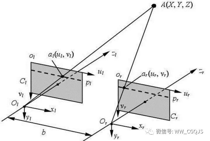
Binocular stereoscopic 3D measurement is based on the principle of parallax. Figure 1 shows a simple schematic view of binocular stereo imaging. The distance between the projection centers of the two cameras is the baseline distance b. The origin of the camera coordinate system is at the center of the camera lens, and the coordinate system is shown in Figure 1. In fact, the imaging plane of the camera is behind the optical center of the lens. In Figure 1, the left and right imaging planes are drawn at the front of the optical center of the lens. The virtual image plane coordinate system is the u-axis and the v-axis of the O1uv and the camera coordinate system. The x-axis and y-axis directions are the same, which simplifies the calculation process. The origin of the left and right image coordinate systems is at the intersections O1 and O2 of the optical axis of the camera and the plane. The corresponding coordinates of a point P in the space in the left image and the right image are P1(u1, v1) and P2(u2, v2), respectively. Assuming that the images of the two cameras are on the same plane, the Y coordinates of the point P image coordinates are the same, ie v1=v2. Obtained by the triangular geometry:

In the above formula (xc, yc, zc) is the coordinate of point P in the left camera coordinate system, b is the baseline distance, f is the focal length of two cameras, and (u1, v1) and (u2, v2) are points P, respectively. The coordinates in the left and right images.
Parallax is defined as the position difference of a point at a corresponding point in two images:

From this, the coordinates of a point P in the space in the left camera coordinate system can be calculated as:

Therefore, as long as a corresponding point in the space on the left and right camera images can be found, and the camera's internal and external parameters are obtained by camera calibration, the three-dimensional coordinates of the point can be determined.
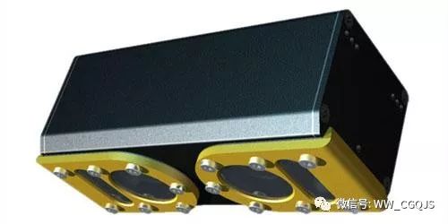
The binocular vision measurement probe consists of two cameras and one semiconductor laser.
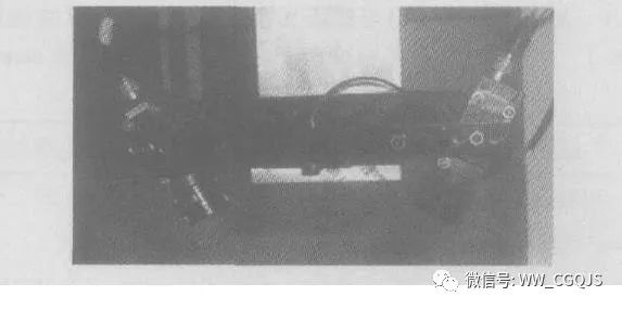

As a light source, a semiconductor laser emits a point of light that is incident on a cylindrical lens and becomes a straight line. The line laser is projected onto the surface of the workpiece as a measurement mark line. The laser has a wavelength of 650 nm and a scanning laser line width of about 1 mm. Two ordinary CCD cameras are placed at an angle to form a sensor for depth measurement. The focal length of the lens affects the angle between the lens's optical axis and the line laser, the distance between the probe and the object to be measured, and the measured depth of field.
Visual measurement is a non-contact measurement based on the principle of laser triangulation. The light emitted by the laser 1 is expanded in a single direction by the lenticular lens to become a light strip, which is projected on the surface of the object to be measured, and the light strip is deformed due to the change of the curvature or depth of the surface of the object, and the image of the deformed light strip is taken by the camera. In this way, the emission angle of the laser beam and the imaging position of the laser beam in the camera can be obtained, and the distance or position of the measured point can be obtained by the triangular geometric relationship.
Similar to the distance that humans use to observe objects with both eyes, the binocular vision measurement sensor captures an image of one strip at the same time through two cameras, and then matches the two images to obtain all the pixels on the strip in two images. Position, using parallax, can calculate the position of the point as well as the depth information. If a coordinate value of the scan line obtained by the scanning mechanism is matched, all the contour information (ie, the three-dimensional coordinate point) of the scanned object can be obtained.
In general, the larger the parallax (x2-x1) of the binocular sensor, the higher the measurement accuracy. It has been found through experiments that increasing the length of the baseline can improve the accuracy of visual measurements. However, for a lens with a focal length, an excessively large baseline length will cause an increase in the angle of the binocular axis, which will cause a large distortion of the image, which is not conducive to the calibration and feature matching of the CCD, but reduces the measurement accuracy. Select 2 lenses with a focal length of 8mm, and find the matching baseline length through experiments to ensure that the binocular vision sensor has higher measurement accuracy within the depth of field of the lens.
Technical characteristics of binocular vision
The realization of binocular stereo vision technology can be divided into the following steps: image acquisition, camera calibration, feature extraction, image matching and 3D reconstruction. The implementation methods and technical features of each step are introduced in turn.
Image acquisition
The binocular stereoscopic image acquisition is performed by two or one camera (CCD) at different positions to move or rotate the same scene to obtain a stereo image pair. Its pinhole model is shown in Figure 1. It is assumed that the angular distance and internal parameters of the cameras C1 and C2 are equal, the optical axes of the two cameras are parallel to each other, the two-dimensional imaging planes X1O1Y1 and X2O2Y2 coincide, and P1 and P2 are the imaging points of the spatial point P on C1 and C2, respectively. However, in general, the internal parameters of the two cameras of the pinhole model cannot be completed the same, and the optical axis and the imaging plane cannot be seen when the camera is installed, so it is difficult to apply in practice.
Relevant institutions have carried out detailed analysis of the relationship between the measurement accuracy of the convergent binocular stereo system and the system structural parameters, and pointed out through experiments that triangulation is performed on a specific point. The measurement error between the point and the angle of the two CCD optical axes is a complex function relationship; if the angle between the optical axes of the two cameras is constant, the greater the distance between the measured coordinates and the camera coordinate system, the greater the error in measuring the distance of the points. . Under the premise of satisfying the measurement range, the angle between the two CCDs should be selected between 50 °C and 80 °C.
Camera calibration
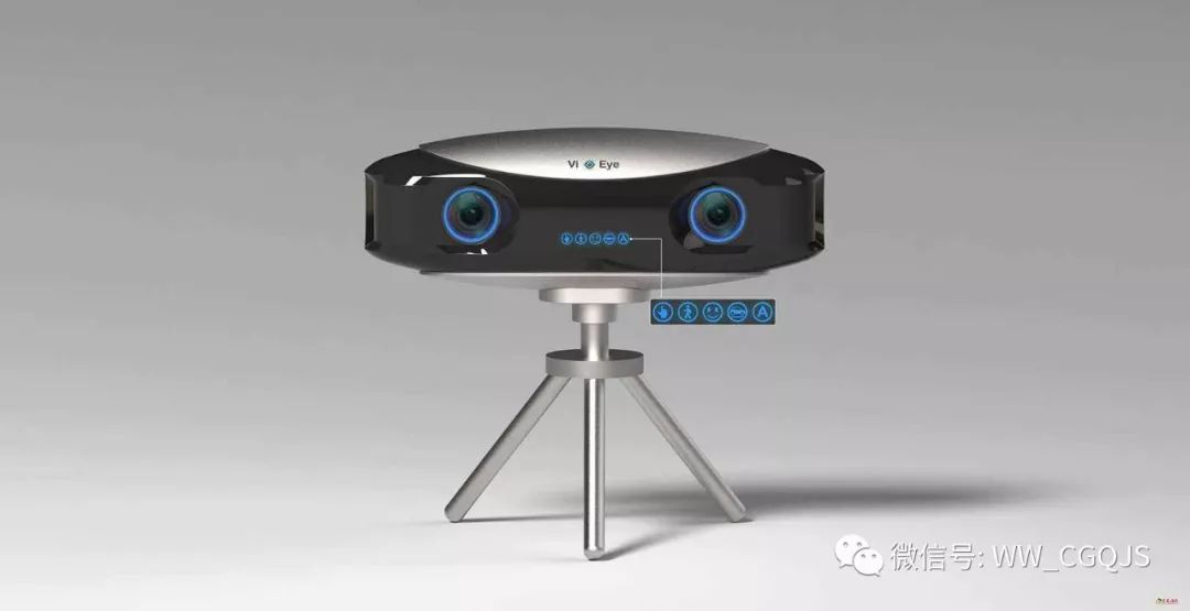
For binocular vision, CCD cameras and digital cameras are the basic measurement tools used to reconstruct the physical world using computer technology. Calibration of them is a fundamental and crucial step in achieving stereo vision. Usually, the single camera calibration method is used to obtain the internal and external parameters of the two cameras respectively; then the positional relationship between the two cameras is established by a set of calibration points in the same world coordinate.
The commonly used single camera calibration methods are:
1. Traditional equipment calibration method for photogrammetry. Using at least 17 parameters to describe the end relationship between the camera and the 3D object space, the amount of calculation is very large.
2. Direct linear transformation. The parameters involved are small and easy to calculate.
3. Perspective transformation short matrix method. The imaging model of the camera is established from the perspective of perspective transformation, and real-time calculation can be performed without initial values.
4. Two-step method of camera calibration. Firstly, the camera parameters of the linear system are solved by the method of perspective short matrix transformation. Then, the obtained parameters are taken as the initial values, the distortion factors are considered, and the nonlinear solution is obtained by the optimization method, and the calibration accuracy is high.
5. Double plane calibration method. In dual camera calibration, precise external parameters are required. Since the structure configuration is difficult to be accurate, the distance and viewing angle of the two cameras are limited. Generally, at least 6 or more known world coordinate points (recommended to take more than 10) are required to obtain a satisfactory parameter matrix, so the actual measurement process Not only is it complicated, but the effect is not necessarily ideal, which greatly limits its scope of application. In addition, the dual camera calibration also needs to consider the nonlinear correction, measurement range and accuracy of the lens. At present, there are few outdoor applications.
Feature point extraction
The feature points that need to be æ’® in the stereo pair should meet the following requirements: adapt to the sensor type and the technique used to extract the features; have sufficient robustness and consistency. It should be noted that the acquired image needs to be pre-processed before the coordinate extraction of the feature point image is performed. Because there is a series of noise sources in the image acquisition process, the image quality can be significantly improved by this processing, and the feature points in the image are more prominent.
Stereo matching
Stereo matching is the most relevant and difficult step in binocular vision. Unlike ordinary image registration, the difference between stereo pairs is caused by the difference in observation points during imaging, rather than by other changes and movements such as the scene itself. According to different matching primitives, stereo matching can be divided into three categories: region matching, feature matching and phase matching.

The essence of the region matching algorithm is to make use of the degree of correlation of grayscale information between local windows, which can achieve higher precision in places with gentle changes and rich details. However, the matching window size of the algorithm is difficult to select. Usually, the window shape technique is used to improve the matching of parallax discontinuities. Secondly, the calculation amount is large and the speed is slow. The coarse-to-fine hierarchical matching strategy can greatly reduce the size of the search space. Cross-correlation operations that are independent of the matching window size can significantly increase the speed of the operation.
The special chip matching does not directly depend on the gray scale, and has strong anti-interference performance, small calculation amount and high speed. However, there are also some shortcomings: the sparseness of the feature in the image determines that the feature matching can only obtain a sparse parallax field; the feature æ’® and positioning process directly affect the accuracy of the matching result. The improvement method is to combine the robustness of feature matching with the compactness of region matching, and extract and locate features by using models that are insensitive to high frequency noise.
Phase matching is a type of matching algorithm developed in the last twenty years. As the matching primitive, the phase itself reflects the structural information of the signal, and has a good suppression effect on the high-frequency noise of the image. It is suitable for parallel processing and can obtain dense parallax with sub-pixel precision. However, there are problems with phase singularity and phase winding, which need to be solved by adding an adaptive filter.
Three-dimensional reconstruction
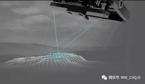
The spatial point reconstruction can be performed under the condition that the corresponding coordinates of the two points in the two images and the two camera parameter matrices are obtained. By establishing four linear equations with the world coordinates of the point as unknowns, the world coordinates of the point can be solved by the least squares method. The actual reconstruction usually uses the outer pole end method. The intersection of the plane consisting of the three points of the optical center of the two cameras and the two imaging planes is called the polar line of the spatial point in the two imaging planes. Once the internal and external parameters of the two cameras are determined, the relationship between the corresponding points can be established by the constraint relationship of the polar lines on the two imaging planes, and thus the equations are connected to obtain the world coordinate values ​​of the image points. The full-pixel 3D reconstruction of the image can only be performed for a specific target, and the calculation amount is large and the effect is not obvious.
Status of binocular vision technology
Foreign status
Binocular stereo is currently used in four areas: robot navigation, parameter detection for micro-operating systems, 3D measurement, and virtual reality.
The Adaptive Mechanical Systems Research Institute of Osaka University of Japan has developed an adaptive binocular vision servo system that uses the principle of binocular stereo vision, such as the relatively stationary three markers in each image as a reference to calculate the target image in real time. The short array is used to predict the next moving direction of the target, and adaptive tracking of the target with unknown motion mode is realized. The system only requires a stationary reference mark in both images, no camera parameters are required. The traditional visual tracking servo system needs to know in advance the parameters of the camera's motion, optics and the movement of the target.
The School of Information Science, Nara University of Science and Technology, Japan, proposed an augmented reality system (AR) registration method based on binocular stereo vision to improve the registration accuracy by dynamically correcting the position of feature points. The system combines single camera registration (MR) with stereoscopic registration (SR), uses MR and three marker points to calculate the two-dimensional coordinates and errors of the feature points on each image, and uses SR and image pairs to calculate feature points. The total error of the three-dimensional position, repeatedly correcting the two-dimensional coordinates of the feature points on the image pair until the total three-dimensional error is less than a certain threshold. This method greatly improves the AR system registration depth and accuracy than using only MR or SR methods. The experimental results are shown in Fig. 2. The three vertices on the whiteboard are used as the feature points of the single camera calibration. The models on the three triangles are virtual scenes. The turtle is a real scene. It is basically difficult to distinguish the virtual scene (dinosaur) and reality. Scene (turtle).

The University of Tokyo in Japan integrated the real-time binocular stereo vision and the overall attitude information of the robot, and developed a dynamic robot navigation system for the simulated robot. The system is implemented in two steps. Firstly, the plane segmentation algorithm is used to separate the ground and obstacles in the captured image pair, and then the information of the robot body posture is used to convert the image from the camera's two-dimensional plane coordinate system to describe the body posture. The world coordinate system establishes a map of the area around the robot; the base performs obstacle detection based on the map established in real time to determine the walking direction of the robot.
Okayama University in Japan developed a visual feedback system using a stereo microscope to control the micromanipulator using a stereo microscope, two CCD cameras, a micromanipulator, etc., for performing cell manipulation, gene injection and micro-assembly of the bell.
The MIT computer system proposes a new sensor fusion method for intelligent vehicles. The radar system provides a rough range of target depth, and binocular stereo vision is used to provide rough target depth information, combined with an improved image segmentation algorithm. The target position in the video image can be segmented in a high-speed environment, and the conventional target segmentation algorithm is difficult to obtain satisfactory results in a high-speed real-time environment.
The University of Washington partnered with Microsoft to develop a wide-baseline stereo vision system for the Mars Satellite "Detector", enabling the "Detector" to accurately navigate the terrain within a few kilometers of Mars that it is about to span. The system uses the same camera to capture image pairs at different locations of the “Detector.†The larger the shooting interval, the wider the baseline, and the farther the landscape can be observed. The system uses nonlinear optimization to obtain the relative position of the camera when the image is taken twice. The robust maximum likelihood ratio method combined with efficient stereo search is used to match the image, and the parallax of sub-pixel precision is obtained, and the parallax is calculated according to the parallax. The three-dimensional coordinates of each point in the image pair. Compared with the traditional stereo system, it can more accurately draw the terrain around the "Detector" and observe the farther terrain with higher precision.
Domestic status
The mechanical system of Zhejiang University fully utilizes the principle of fluoroscopic imaging, and adopts the binocular stereoscopic method to realize the dynamic and accurate pose detection of multi-degree-of-freedom mechanical devices. It only needs to extract the three-dimensional coordinates of the necessary feature points from the two corresponding images. The amount is small, the processing speed is fast, and it is especially suitable for dynamic situations. Compared with the hand-eye system, the motion of the measured object has no effect on the camera, and it is not necessary to know the prior knowledge and constraints of the motion of the measured object, which is beneficial to improve the detection accuracy.
Based on binocular stereo vision, the Department of Electronic Engineering of Southeast University proposes a new method for minimizing the stereo matching of the gray-scale multi-peak parallax absolute value, which can perform non-contact precision measurement on the three-dimensional space coordinates of three-dimensional irregular objects (deflection coils). .
Harbin Institute of Technology adopted a heterogeneous binocular activity vision system to achieve full autonomous soccer robot navigation. A fixed camera and a horizontally rotatable camera are mounted on the top and bottom of the robot, which can simultaneously monitor different azimuth viewpoints, reflecting the superiority of human vision. Through reasonable resource allocation and coordination mechanism, the robot can achieve the best match in the field of view, the accuracy of the heel and the processing speed. The binocular coordination technology allows the robot to capture multiple effective targets at the same time, and through data fusion when observing the encounter targets, the measurement accuracy can also be improved. In the case of other sensors failing in the actual game, full-autonomous soccer robot navigation can still be achieved by relying solely on binocular coordination.
The development direction of binocular vision technology
As far as the development of binocular stereo vision technology is concerned, there is still a long way to go to construct a universal binocular stereo vision system similar to the human eye. Further research directions can be summarized as follows:
1. How to establish a more effective binocular stereo vision model can more fully reflect the essential properties of stereo vision without definiteness, provide more constraint information for matching, and reduce the difficulty of stereo matching.
2. Exploring new computational theory and matching effective matching criteria and algorithm structures for comprehensive stereo vision to solve the existence of grayscale distortion, geometric distortion (perspective, rotation, scaling, etc.), noise interference, special structure (flat area , repeat similar structures, etc., and cover the matching problem of the scene;
3. The algorithm develops toward parallelization, speeds up, reduces the amount of calculation, and enhances the practicability of the system;
4. Emphasize the constraints of scenes and tasks, and establish a purpose-oriented task-oriented binocular stereo vision system for different application purposes.
Binocular stereo vision, a discipline with broad application prospects, will continue to advance with the development of optics, electronics and computer technology, and will become practical, not only into industrial testing, biomedicine, virtual reality and other fields. At present, binocular stereo vision technology has been widely used in production and life, and China is in the initial stage, and it is still necessary for the majority of science and technology workers to work together to contribute to its development. Among the many factors that rely on the universal development of machine vision, there are both technical and commercial aspects, but the demand for manufacturing is decisive. The development of the manufacturing industry has brought about an increase in the demand for machine vision. It also determines that machine vision will be collected, analyzed, transmitted, and judged by the past, gradually moving toward an open direction. This trend also indicates the machine. Vision will be further integrated with automation. Demand determines the product, and only the product that meets the demand has room for survival. This is the same law, and so is machine vision.
Stand Table Fan ,12 Inch Oscillating Table Fan,Pedestal Table Fan,Height Adjustable Table Fan
Foshan Shunde Josintech Electrical Appliance Technology Co.,Ltd , https://www.josintech.com