Electronic technology has developed rapidly in recent years. DC switching power supplies are widely used in personal computers, telecommunications, systems, aerospace and biomedical fields. They have a wide range of electronic systems for switching power supply performance, power density, work efficiency and reliability. Application, miniaturization has become an inevitable requirement. This paper introduces the design of DC chopping BUCK circuit.
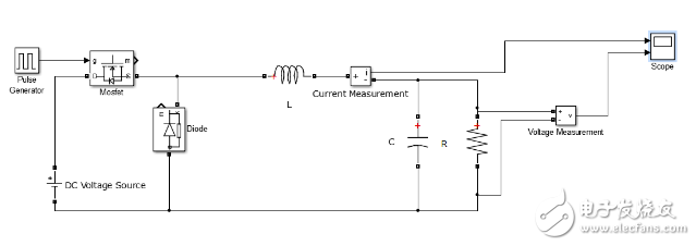
Buck main topology circuit open-loop Buck circuit diagram
Open loop buck circuit
Parameter calculation and selection(1) Duty cycle D = U0 / UI = 75%
(2) Filter inductor
The selection of the filter inductor is related to the range of the load current and the desired operating state. If the circuit is required to operate in the continuous operation of the inductor current, the critical inductance L=(1-D)U0/(2fsI0) can be calculated according to the formula:
L=7.5*10(-6)H
At this time, the L value is a critical value of the continuity of the inductor current, and the actual inductance value may be selected as a critical inductance of (2 to 3) times. Here L takes 7.5*10(-6)H.
(3) Filter capacitor
The capacity of the capacitor affects the output ripple voltage and the amount of overshoot. When the switch is turned off to supply power to the load and reduce the ripple of the output voltage, the selection of the filter capacitor C is directly related to the ripple voltage component U in the output of the switching regulator power supply.
Filter capacitor C
C=U0(1-D)8U0LF2
Calculated according to the ripple requirement, C=0.0007F
Here capacitor C is 7.5*104F.
The ripple voltage is mainly determined by the parasitic resistance ESR and capacitance of the capacitor. In general, the product of C and the parasitic resistance Rc tends to be constant, about 50-80 μΩ∗F. In this example, it is taken as 60 μΩ∗F. So Rc = 0.08 Ω.
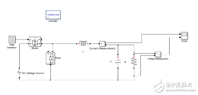
Open-loop BUCK circuit model and simulation(1) Set up a simulation model of the Buck circuit in simulink, and use the switching device as a MOSFET, as shown in the following figure.

Open loop buck circuit model in matlab

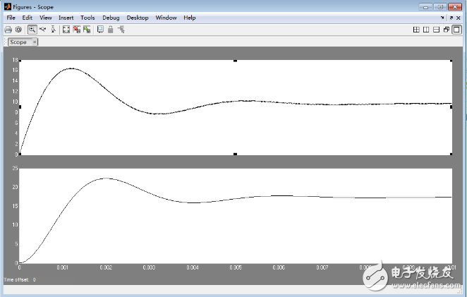
Simulate voltage and current waveforms
Nanning Ousibang Information Technology Co., Ltd. , https://www.ousibangvape.com