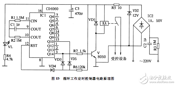
The circuit can set the cycle time of the device and the time of each work, and the device can be continuously cycled according to the set time, and can be applied to control occasions such as timed pumping, timed ventilation, and timing ventilation.
Circuit working principle: After the circuit is stepped down by capacitor C2 and bleeder resistor R3, it is rectified by bridge reactor IC2. After VD2 is regulated, DC voltage of about 12V is obtained, which supplies power to IC1 and other circuits. IC1 is a 14-bit binary counter/divider integrated circuit that provides a clock pulse for IC1 timing by a clock oscillator of a certain frequency formed by the internal circuits of R1, R2, C1, and IC1. When the circuit is energized, it first enters the working gap waiting time of the device. IC1 internally realizes the delay by counting and dividing the clock pulse. When the timing time is up (according to the parameter in the figure, it is about 3 hours), the Q14 end of IC1 The output is high, so that the transistor V is turned on, and the relay KA gets a point to drive the controlled device to start working. At this point, IC1 starts to count the working time of the device again. When the timing time is up (about 20 minutes according to the parameters in the figure), the Q14 end of IC1 changes to low level again, so that V is cut off and the device stops working. At this time, IC1 is automatically reset, and the next timing is started again, so that the device can perform the timing cycle according to the set time. In the figure, VL is the work indicator.

Component selection: IC1 selects 14-bit binary counter/divider integrated circuit CD4066, and can also use CC4066 or other digital circuit blocks with the same function. IC2 selects 1A, 50V bridge stack, and can also be connected with four 1N4007 diodes. Transistor V uses NPN type triode 8050, and can also use domestic triodes such as 9013 or 3DG12. VD1 selects rectifier diode 1N4007; VD1 selects 1W, 12V silicon voltage regulator tube, such as 1N4742; VD3 ~ VD5 uses switching diode 1N4148; VL selects ordinary light-emitting diode. Resistors R1, R2, R4, R6 and R7 use 1/4W metal film resistors; R3 and R5 use 1/2W carbon film resistors. C1 selects polyester or monolithic capacitors; C2 selects polypropylene capacitors with a withstand voltage of 450V and above; C3 selects aluminum electrolytic capacitors with a withstand voltage of 16V. KA selects a miniature relay with a coil voltage of 12V, and the contact capacity is determined according to the power of the controlled device. After the circuit is installed, it can work normally without debugging. When the control time needs to be adjusted, the parameters of R1 and C1 can be adjusted; or the position of the IC1 output control terminals (Q4 to Q14) can be changed.
What is a Capsule Slip Ring?
Capsule slip rings are a type of electrical connector that are used to transfer power and data between two rotating objects. They are commonly used in applications where there is a need to send or receive signals from a stationary object to a rotating one, or vice versa.
How Does it Work?
Capsule slip rings work by using a series of electrical contacts that rotate with the object on which they are mounted. These contacts are spaced evenly around the circumference of the ring, and as they rotate they make and break contact with corresponding contacts on the other object. This allows power and data to be transferred between the two objects without any interruption.
Advantages of Capsule Slip Rings
There are several advantages to using capsule slip rings in place of other types of electrical connectors.
For example, the rotation of the contacts causes them to be freely accessible and therefore free from dust and debris. This makes them ideal for applications where connector maintenance is often a problem.
Because the contacts are freely accessible, they can be readily replaced if a fault occurs. They also have very low electrical resistance, making them ideal for transmitting radio frequency signals. Because of the low resistance, this type of connector is often used in high-speed data transmissions.
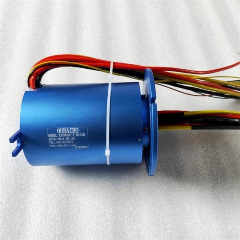
This type of Conductive Slip Ring is similar to the shape of a hat. The brim part is a flange with a conductive slip ring. The function of the flange is to facilitate installation. It is connected to electrical equipment through the fixing hole of the flange. It can be firmly installed on the equipment. Therefore, the stator of the cap-type slip ring is generally fixed by the outer layer with a flange, and the inner part is the rotor with the inner shaft rotating. The stator and the rotor are not fixed, and the details will be different according to the installation method.

Capsule Slip Ring,Split Ring Motor,Slip Ring Motor Connection,Slip Rings In Synchronous Motor
Dongguan Oubaibo Technology Co., Ltd. , https://www.sliprobs.com