In the field of optical communication, larger bandwidth, longer transmission distance, and higher receiving sensitivity are always the pursuit goals of researchers. Although wavelength division multiplexing (WDM) technology and erbium-doped fiber amplifier (EDFA) applications have greatly improved the bandwidth and transmission distance of optical communication systems, along with the application of communication technologies such as video conferencing and the spread of the Internet. Explosive growth puts higher transmission performance requirements on the physical layer that is the basis of the entire communication system. The optical communication system adopts intensity modulation/direct detection (IM/DD), that is, the transmitter modulates the optical carrier strength, and the receiver performs envelope detection on the optical carrier. Although this structure has the advantages of simplicity, easy integration, etc., since the ASK modulation format can only be adopted, the single channel bandwidth is limited. Therefore, this traditional optical communication technology is bound to be replaced by more advanced technology. However, today, when the communication bubble bursts, the application of new optical communication technologies will inevitably bring about the demand for new communication devices, the high cost of high-speed communication equipment replacement in the face of high optical device prices. It is unacceptable to operators, so for equipment manufacturers, the development of new fiber-optic communication technologies is also facing great risks. How to improve the performance of optical communication systems based on existing equipment has become a practical problem. In this context, coherent optical communication technology, which was highly hoped more than 20 years ago, was once again placed on the desktop.
The theory and experiment of coherent optical communication began in the 1980s. Since coherent optical communication systems are recognized as having high sensitivity, countries have done a lot of research work on coherent optical transmission technology. After ten years of research, coherent optical communication has entered a practical stage. A series of coherent optical communication experiments have been carried out in countries such as the United Kingdom, the United States and Japan. At 1989 and 1990, AT&T and Bell conducted a 1.7 Gbit/s FSK field-free relay-free coherent transmission experiment with 1.3 μm and 1.55 μm wavelengths between the Rolling-Crick ground station and the Sunbury hub in Pennsylvania. , 35 kilometers apart, the receiving sensitivity reaches -41.5dBm. In 1990, NTT conducted a 2.5Gbit/s CPFSK coherent transmission experiment between the Oita-Yinyu and Wu stations in the Seto Inland Sea, with a total length of 431 kilometers. Until the end of the 1880s, the development of EDFA and WDM technology slowed the development of coherent optical communication technology. During this period, sensitivity and information capacity per channel are no longer of concern. However, after 20 years of development and widespread application of the WDM system for direct detection, new signs have begun to appear, marking the application of coherent optical transmission technology will once again be taken seriously. In terms of digital communications, expanding the capacity of C-band amplifiers, overcoming the deterioration of fiber dispersion effects, and increasing the capacity and range of free-space transmission have become important considerations. In terms of analog communication, sensitivity and dynamic range become key parameters of the system, and they can all be greatly improved by related optical communication technologies.
This design will use PIC32 microcontroller as the main control system, design a suitable coherent optical communication system, and can carry out the purpose of information code transmission in the system to complete this design.
system structure:As shown in the following figure: This system mainly completes the signal modulation control and system synchronization control of the front end of the coherent light. The transmitting end includes a raw light control system and an electro-optical control system, including amplitude modulation and phase modulation, which will be the main control work of the PIC microcontroller.
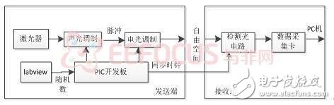
The laser (SDL5412) emits continuous light, and a synchronous clock is required during signal transmission to enable the transmitter and receiver to synchronize. In the design of the system, the continuous laser generated by the light source is acousto-optic modulated to generate a pulsed light signal as a synchronization signal at the receiving end.
1 Acousto-optic modulator:The acousto-optic modulator (MT80-B30A1-IR) used in this system integrates an acousto-optic medium, an electro-acoustic transducer, a sound absorption (or reflection) device, and the like. The acousto-optic crystal used in the modulator is TeO2.
TeO2 crystal is a kind of acousto-optic material with high quality factor. It has good birefringence and optical rotation. The speed of sound propagation in the [110] direction is slow. It has fast response, small driving power, high diffraction efficiency, stable and reliable performance, etc. advantage. It is an ideal single crystal material for various acousto-optic devices such as acousto-optic deflectors, modulators, resonators, and tunable filters.
2 Modulated signal driver:The acousto-optic modulation signal in the system is generated by a direct digital synthesizer (DDS), which can easily realize digital control of the output frequency and amplitude. The control port of the DDS source has 31-bit frequency control and 8-bit amplitude control.
3 control module design:The control module realizes the control of the acousto-optic modulation signal driver to generate a radio frequency signal with a frequency of 80 MHz and a pulse wave to drive the acousto-optic modulation crystal for acousto-optic modulation.
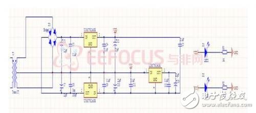
The control module is mainly implemented by the PIC microcontroller plus the peripheral control circuit. Since the number of pins required for control is large (31-bit frequency control, 1-bit frequency lock, 8-bit amplitude control, 1-bit external trigger bit, a total of 41 bits), the main control MCU is implemented by PIC series, using 2-bit setting. Fixed frequency, 8 bits set amplitude, 1 bit trigger. Figure 2 below shows the acousto-optic modulation hardware structure diagram:
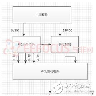
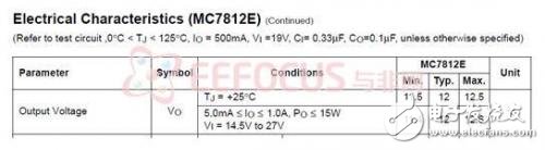
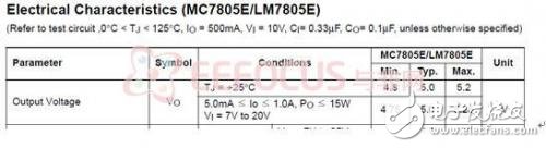
When designing the circuit, first consider using a transformer to step down to a suitable voltage. After rectification and filtering, it is regulated by a voltage regulator chip. The output voltage of the integrated voltage regulator is relatively small. The suitable integrated chip is mainly 5V and 12V output. Choose to use 24 MC7812 or LM7812 to provide 24V voltage, one MC7805 or LM7805 to provide 5V, the circuit is kept at 500MA.
Armored Cable,Duplex Amoured Cable,Armoured Fiber Optical Cable,Amored Fiber Cable
ShenZhen JunJin Technology Co.,Ltd , https://www.jjtcl.com