Conventional pull-line displacement sensors use a potentiometer-type displacement sensor that converts mechanical displacement into a resistive or voltage output that is linear or arbitrary as a function of the potentiometer element. Both the ordinary linear potentiometer and the circular potentiometer can be used as linear displacement and angular displacement sensors, respectively. However, a potentiometer designed to achieve the purpose of measuring displacement requires a certain relationship between the change in displacement and the change in resistance. The movable brush of the potentiometer type displacement sensor is connected to the object to be measured, and the displacement of the object causes the resistance of the moving end of the potentiometer to change. The amount of change in resistance reflects the magnitude of the displacement, and the increase or decrease in the resistance indicates the direction of the displacement. Usually, the power supply voltage is applied to the potentiometer to convert the resistance change into a voltage output. The conventional pull-type displacement sensor has a stepwise change in the output resistance of the resistor due to the stepwise change of the resistance of the resistor when the brush is moved. If such a displacement sensor is used as a displacement feedback element in a servo system, an excessive step voltage will cause the system to oscillate. Therefore, the resistance value of each turn should be minimized in the fabrication of the potentiometer. At the same time, another major disadvantage of potentiometer sensors is that they are subject to wear, poor resolution, low resistance, and poor high frequency characteristics, resulting in a decrease in measurement accuracy. Its advantages are: simple structure, large output signal, convenient use and low price.
The wire-type displacement sensor based on the magnetic sensitivity angle technology uses the magnetic field as the transmission carrier to convert the displacement transformation into the angular displacement of the magnetic field, and at the same time, returns the displacement signal to the application system through the communication interface.
1 overall design
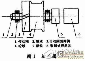
The function of the wire-type displacement sensor based on the magnetic sensitivity angle technology is to replace the mechanical displacement of the wire into an electrical signal that can be measured, recorded or transmitted, mainly composed of an automatic return spring, a hub, a magnet and a data processing unit. 1 is shown.

It can be seen from Fig. 1 that the wire-type displacement sensor based on the magnetic sensitivity angle technology is mainly composed of six parts, which changes the traditional contact type displacement sensor, such as contact type, easy wear and high frequency characteristics, and the like, based on the magnetic sensitivity angle technology. The pull-line displacement sensor converts the mechanical displacement change into the magnetic field angle change by using the magnetic field as the medium. On the one hand, it solves the contact mode of the traditional pull-line displacement sensor, on the other hand, it reduces wear and improves the high-frequency characteristics of the system, thereby ensuring the accuracy of displacement detection. The data processing operator is configured to calculate, by the mathematical model, the received magnetic sensitivity angle signal as a displacement signal of the cable. The communication interface communicates with the device of the application system through the communication interface, receives the command from the application system device, and feeds back the collected displacement signal to the application system. Thereby improving the accuracy, stability and reliability of data acquisition, and reducing the application threshold of the displacement sensor.
The function of each component is described as follows:
(1) The steel wire of the cable is wound around the hub, and the hub is connected with a magnet. When the wire is displaced, the rotation of the hub is driven, and the rotation of the hub causes the magnet connected to the shaft of the hub to rotate, so that the magnetic field of the magnet is generated. A changing angle. When the pull motion occurs, the automatic return spring ensures that the pull wire has a certain tension, ensuring the proportional relationship between the displacement of the pull wire and the magnetic sensitivity angle.
(2) The magnetic sensitivity angle sensor and the magnet are mounted on the same central axis for sensing the change of the angle of the magnet, and a microprocessor is selected, which reads the magnetic sensitivity angle information and establishes a magnetic model by establishing a mathematical model. The angle is calculated as the displacement of the wire.
(3) A communication interface, the microprocessor receives a command from the application system through the communication interface and returns the displacement information to the application system through the communication interface.
2 hardware interface circuit design
The data processing unit is composed of a magnetic sensitivity angle sensor, a microprocessor unit, a communication interface and an output module. The specific functional block is shown in FIG. 2 .

By analyzing Figure 2, the magnetic sensitivity angle sensor uses MLX90316, which converts the angle of rotation of the magnet magnetic field caused by the displacement of the cable into a magnetic sensitivity angle. The microprocessor unit selects 32-bit embedded ARM for processing the received magnetic sensitivity angle data to complete the reception of the magnetic sensitivity angle data. Since the received magnetic field is converted, the mathematical model is combined with the hub. The diameter is converted into the displacement of the wire by factors such as the diameter. Therefore, in order to enable data reception and model establishment quickly, LPC2136 is selected as the data processing unit. The input and output control modules are responsible for processing various external interfaces, such as receiving commands from the application system through the communication interface, and returning the collected displacement results to the application system, so that the microprocessor unit can execute the commands of the application system and collect the results. It is safely and reliably transmitted to the application device through the interface, mainly including one RS 485 and 4 to 20 mA current output.
2.1 Magnetic sensitivity angle receiving interface
The MLX90316 is a linear Hall chip that uses a planar integrated Hall sensor technology to measure the flux density coplanar with the surface of the chip. It can be rotated from 0 to 360°. The position value outputs a highly accurate linear absolute position signal through multiple modes, and is low in cost and easy to install.
The front end of the MLX90316 chip is a sensor using Triaxis Hall technology. The two orthogonal analog signals obtained by the Hall sensor are amplified, and then enter the chip microprocessor (DSP) through the 14-bit differential A/D converter, and then the digital signal processed by the 16-bit DSP is divided into three channels. Output. The MLX90316 output has 12-bit angular resolution, 10-bit angular accuracy, and to some extent avoids the effects of external temperature changes on output accuracy. The MLX90316 has three outputs: a 12-bit D/A conversion to an analog output; a PWM output with a frequency of 100 to 1 000 Hz; and a serial communication protocol output (SPI) in digital mode.
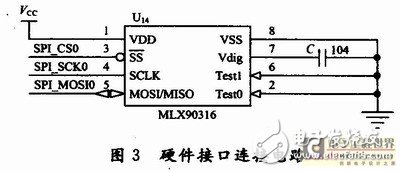
Since the output signal of serial communication comes directly from the internal DSP output of the MLX90316, the SPI output mode is more stable, the error is smaller, and it has higher anti-interference ability. In this design, the SPI interface is selected, and the specific hardware interface connection circuit is shown in Figure 3. In Figure 3, the SPI three lines of the MLX90316 are connected to the SP10 port of the ARM LPC2136. The SPI (SerialProtocol InterIace) bus interface is a synchronous serial peripheral interface. This is a serial interface protocol for 4 signal lines, including master and slave modes. The four signal lines are: clock line (SCK), data input line (MISO), data output line (MOSI), and slave enable line (SS).

Non-Shielded Control Cable YY CVV LIYY
Low Voltage Control Cables
Standard applied: IEC60227, BS 6500
Rated Voltage: 300/500V 450/750V 0.6/1kV
Others: Fire Cable and other property Low Voltage Power Cable can be available
Applications: Those Control Cables are suitable for fixed installations as connection and inter-connection cables in general machine,production lines.
Non-Shielded Control Cable Yy Cvv Liyy,Non-Shielded Control Cable Yy,Non-Shielded Control Cable Cvv,Non-Shielded Control Cable Liyy
Shenzhen Bendakang Cables Holding Co., Ltd , https://www.bdkcables.com