introduction
With the continuous development of new technologies, digital substations are emerging. Driven by smart grid planning, digital substations will become the mainstream of new substations in the future. As we all know, the grid signal quantity is extremely large and the correlation is very strong, which brings great trouble to the collection calculation and real-time monitoring. To solve this problem. The designer of this article builds intelligent IED (Intelligent Electronic Device) based on DSP and CPLD, which can collect multiple signals at the same time, and obtain the key data of grid operation through FFT algorithm.
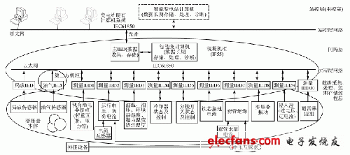
The logic of the intelligent substation based on IEC61850 is shown in Figure 1. The IEC61850 protocol mainly defines the information hierarchical structure of the substation: process layer, station control layer and bay layer. This article focuses on intelligent IED devices. According to the description of the IEC 61850 protocol, the IED detection devices are located at the bay and process layers. Among them, the main IED responsible for storing measurement data, performing power grid data analysis and diagnosis is located at the bay layer; the measurement IED directly connected to the field sensors is located at the process layer; the existing computer system of the substation at the station control layer will store long-term historical data and diagnosis result.

Figure 1 Logic block diagram of intelligent substation
1 System hardware design
The system consists of an algorithm module built by DSP, CPLD and high-speed A / D converter, a multi-way selection data acquisition module and a signal filtering module. Responsible for DSP acquisition is the current mainstream industrial control DSP, CPLD uses Altera's EPM3256, A / D converter uses Maxim's 14-bit high-speed chip MAX125. DSP focuses on the calculation of energy quality of the power grid, and the circuit constructed by CPLD and high-speed A / D converter is suitable for the simultaneous acquisition of multiple signals.
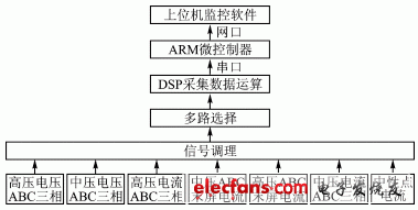
The intelligent IED processing flow is shown in Figure 2. The detected signals are mainly three-phase voltage and three-phase current signals. The signal front-end circuit will perform a low-pass filtering function to filter out clutter that has a greater impact on the signal. Then the signal is collected by the high-speed A / D converter, realized by the A / D converter + CPLD circuit, and finally sent to the DSP through the data bus. After the parameter calculation is completed, the DSP unifies the data format and uploads it to the main control IED. Its main function is to receive and detect the data of the IED and upload it to the database.

Figure 2 Intelligent IED processing flow
1.1 Multiple selection switch
There are many objects collected by this system. Since the calculated power factor angle and dielectric loss angle must be the phase difference between the voltage and current at the same time, the three-phase current value and the three-phase end screen corresponding to the three-phase voltage must be collected simultaneously Current value. MAX125 is a dual-channel 8-channel acquisition, each channel can collect 4 signals, 3 of them will be used in this system, and the other signal can be idle.
1.2 Communication interface with host computer
In fact, this system is just a data acquisition module of the entire intelligent transformer. After processing all the collected signals, they must be packaged and passed to the host computer. This system uses a simple RS232 transmission method. Transmit all the data to the host computer at one time, and then pass it to the monitoring center through TCP / IP after being packaged by the host computer.
1.3 Data acquisition and A / D conversion module
The smart grid also needs to collect at least 20 signals. Including high school three-phase voltage, three-phase current, three-phase last screen current and neutral point current. These signals are converted into voltage signals by the sensor and input to the monitoring device.
The system requires that the harmonic content of more than 13 times be calculated, and the FFT algorithm collects at least 128 points in 2 grid cycles. The grid frequency is 50 Hz, which means that 128 operating points must be acquired in 40 ms, and the acquisition frequency is 3 200 Hz. In order to ensure that the collected points are concentrated in two complete cycles, it is necessary to use the DSP to periodically interrupt the collection points. In the entire system, the conversion accuracy of the signal acquisition unit plays a vital role in the performance of the entire system. The MAX125 comes with a sample and hold device. The channels are sampled at the same time, and the sampling precision is 14 bits. It is suitable for simultaneous sampling of voltage and current at a certain moment in the power grid; the input voltage range is ± 5 V, and the time for collecting one channel is 3 μs. .
When the MAX125 converts the sampled 8-channel signal, its INT pin generates an interrupt signal, which is connected to the custom INT pin in CPLD to indicate that the conversion is completed. The DSP can read and process the sampled signal by responding to the interrupt. MAX125 realizes the channel selection by programming the address lines of A0 ~ A3. The CLK signal is used as the clock required for A / D conversion and is provided by the CPLD clock. MAX125's data bus (D0 ~ D13), clock input CLK, chip select input CS, write input WR, read input RD, conversion start input CONVST and interrupt output INT pin, all with the corresponding corresponding function I / O customized in CPLD The pins are connected. Because this system needs to collect 20 front-end signals synchronously, and MAX125 is an 8-channel differential input A / D conversion chip, so this system requires 3 MAX125 chips.
1.4 Signal conditioning circuit
Signals derived from transformers of 220 kV or above must enter the sensor after a complex environment on site. The signal from the sensor to the MAX125 is also transmitted over a long line. Its signals cannot usually be directly received by the control unit, so the signal conditioning circuit becomes an essential part of the control system. Generally speaking, the 20 mA standard current signal is converted into a standard voltage signal of 1 ~ 5 V at the differential input terminal, and then input into the A / D converter after conditioning by the signal conditioning circuit. The output voltage is higher than the input voltage value of the A / D converter, which is sampled after voltage division.
A large number of non-linear loads in the power system will greatly reduce the power quality of the power grid. If the signal collected from the power grid does not do any processing, it will affect the arithmetic accuracy of the DSP. The signal processing in this system uses a low-pass filter. Low-pass filter modules generally use circuit components (such as resistors, capacitors, and inductors) to form the required frequency characteristic circuit. An ideal low-pass filter can completely eliminate all frequency signals above the cut-off frequency, and signals below the cut-off frequency can pass through unaffected.
2 System software design
2.1 Software flow
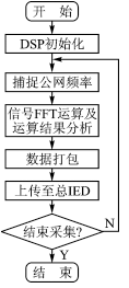
The first is the initialization of DSP's corresponding functions, including serial port, timer interrupt, and some I / O ports used as control lines. Before data processing, an EVA module must be turned on to capture the frequency of the power grid. The subsequent work is to read the data from the A / D converter, a group of 128 corresponding to the voltage and current of the last cycle of the two cycles. Each 128 data is separately subjected to FFT operation, and the results of the operation will be further analyzed to obtain values ​​such as power factor and dielectric loss angle. The process of IED data collection, calculation and upload is shown in Figure 3.

Figure 3 IED data collection, calculation, upload process
The parameters that need to be calculated by DSP are the effective values ​​of three-phase voltage and three-phase current of high voltage A, B and C, the effective values ​​of three-phase voltage and three-phase current of medium voltage A, B and C, and 2 to 13 Wave amplitude and harmonic distortion rate, as well as the power factor and dielectric loss angle value of high and medium voltage three phases. The problem to be solved by the DSP algorithm is to calculate the power factor of 2 ~ 13 harmonics and each phase. The core of the algorithm is the FFT algorithm.
There are some draft products here, which will not be displayed on the website. These products can be modified later to enrich the content of the website. If you want to know more about our company, you can go to our website to check, there will be what you want, or you can consult us. Nice to meet you and looking forward to our cooperation.
Draft-waiting For Releasing,Draft-waiting For Releasing,Draft-waiting For Releasing
ETOP WIREHARNESS LIMITED , https://www.etopwireharness.com