In this paper, ARM7 is used as the main control chip, and a smart desoldering and reflow soldering station control system is designed. It can be controlled by keyboard operation, and its status and real-time temperature curve can be displayed through the liquid crystal display. Demolition and welding, suitable for repair and processing of integrated circuit boards.
Hardware circuit
It is mainly composed of a transformer, a rectifier diode, a filter capacitor, an integrated voltage regulator, etc., and provides a stable voltage of 5V, 3.3V, and 1.8V for the circuit.
Signal detection circuit module
Mainly composed of thermocouple, operational amplifier 27L2, DS18B20 and ARM7 internal AD. The temperature is converted to a digital signal recognizable by the processor.
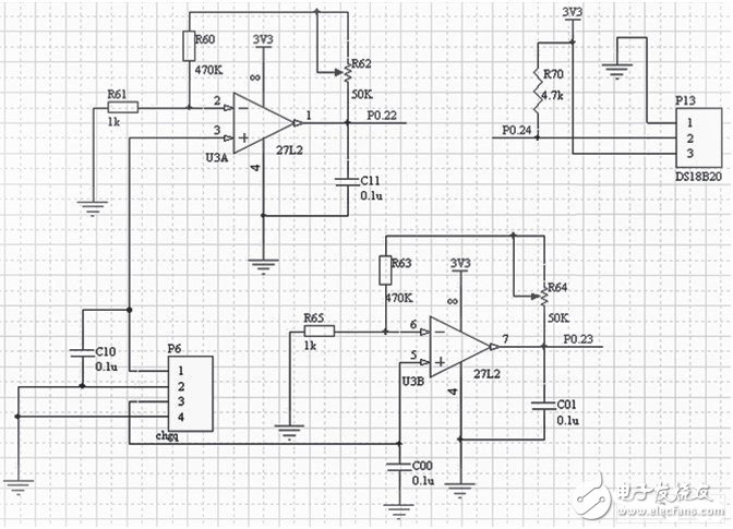
Figure 2 temperature acquisition circuit
The temperature acquisition circuit of this design is shown in Figure 2. The 1 and 3 pins of the P6 port are connected to the positive terminal of the thermocouple sensor, and the 2 and 4 pins are connected to the negative terminal of the thermocouple sensor. After the thermocouple collects the signal, it filters out the high frequency noise through C00 and C10 (high frequency filter capacitor), and then amplifies the signal through 27L2 (low frequency small signal amplifier). The ratio of the sum of R64 and R63 to R65 is U3B. Magnification, similarly, the ratio of R60 to R62 and R61 is the magnification of U3A. After amplification, the high frequency noise is filtered by C01 and C11, and finally the signal is transmitted to ARM7, and the analog voltage signal is converted into a digital signal recognizable by the processor through its internal AD converter. When the temperature of the probe part of the thermocouple sensor changes, the voltage across the thermocouple sensor also changes according to a certain proportion, and then the voltage signal is amplified by 27L2, and then the analog quantity is converted into a digital quantity by the ARM internal AD, the ARM processor Once you get the digital amount, you know the current temperature. Of course, it is not enough to accurately measure the temperature of only the thermocouple temperature measurement module.
Because the thermocouple sensor has a defect, the temperature measured by it is the temperature difference between the probe and the cold end. That is to say, if only the above circuit is used for temperature measurement, only the temperature measured at the cold junction temperature is zero. It is the most accurate. The greater the temperature difference between the cold junction temperature and the zero point, the less accurate the measured temperature data. In this design, while the soldering station is heated, the temperature of the cold junction of the thermocouple changes, which results in inaccurate temperature measurement. In order to solve the above problem, the DS18B20 has been specifically added as a compensation, which is called the correction coefficient correction method in the industry.
ARM minimum system circuit module
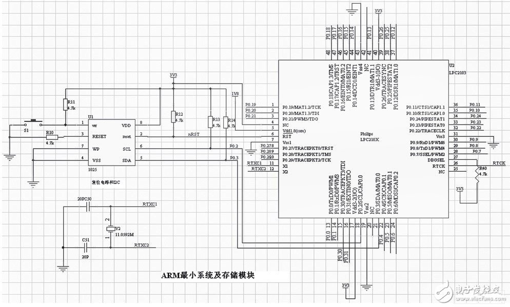
Figure 3 ARM minimum system and external storage circuit diagram
This design uses ARM7 as the main control chip, mainly because of its high cost performance, rich resources, stable and reliable work. It features 32kB of on-chip Flash program memory and 8kB of on-chip static RAM; 128-bit wide interface/accelerator for up to 70MHz operation; 10-bit A/D converter with 8 inputs; 2 32-bit timer counters and Two 16-bit timer counters; up to 32 general-purpose IO ports that can withstand 5V; multiple serial interfaces, including two UARTs, two I2C buses, SPI, and SSP with buffering and variable data lengths; Up to 13 edge, level-triggered external interrupt pins; a programmable on-chip PLL for up to 70MHz CPU operation frequency and more.
In the ARM minimum system of Figure 3, the 11.0592M crystal and two 20pF capacitors provide a stable operating frequency for the system, and then the ARM internal phase-locked loop multipliers to operate up to 70MHz. U1 in the figure is CAT1052, which provides a stable reset circuit for the system, and provides the system with 256 bytes of readable and writable E2PROM, so that the system stores power and does not lose data space.
Execution circuit module
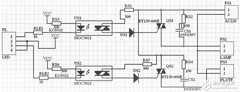
Figure 4 Execution module circuit diagram
The execution circuit of this design is shown in Figure 4. The PL port is connected to the control indicator, PS1 is the AC220 interface, PS2 is the lamp body interface, PS3 is the hot plate interface, and the network labels KONG1 and KONG2 are connected to the two control pins of the ARM. When the ARM detects that the current temperature is lower than the corresponding temperature on the temperature curve (ie, the temperature that is currently required to be heated), the ARM processor sets the corresponding control port to zero, and the corresponding photocoupler (US1 or US2) is emitted. The terminal works to make the receiving end conduct. At this time, the power supply voltage reaches the trigger pole of the triac (QS1 or QS2) through the trigger diode (DS1 or DS2) and the 300Ω resistor, so that the heating plate or the lamp head starts to heat up. . Similarly, when the control terminal of the ARM gives a low level, the corresponding thyristor is turned off, and the lamp or the heating plate stops heating.
The Cutting Machine is a product developed for Cutting TPU Protective Films, Hydrogel Screen Protective Films and PVC Back Stickers.
Advantages of Cutting Machine:
1. "0" inventory, no need to worry about large inventory.
2. Compatible with "99%" 6000+ mobile phones, watches, tablets, etc.
3. According to needs-customize the Protective Film that customers want at any time.
4. Will not lose sales opportunities due to shortages.
5. Save product packaging and transportation costs.
6. Say goodbye to the losses caused by unsold old inventory.
7. No need to spend time and energy to find various types of products.
8. Selling new products for the first time.
9. Different styles of Protective Film can be customized.
10. Simple operation, align and paste it on the device, just one step.
11. Green environmental protection, reduce packaging, reduce waste and reduce costs.
12. To meet the needs of more customers.
13. Add value and increase sales for mobile phone stores, offline stores, and value-added services.
14. Exclusive policy, regional guarantee, first come first served.
15. Lead opponents, lead the market, and seize opportunities.
16. Regain retail market share and create higher value space.
17. New generation mobile internet Mobile Phone Protective Film customization system.
18. Quickly start the business model and start the retail business easily.
Hydrogel Cutting Machine, Mobile Phone Screen Protector Cutting Machine, Hydrogel Film Cutting Machine, Hydrogel Protective Film Cutting Machine, Hydrogel Machine
Shenzhen Jianjiantong Technology Co., Ltd. , https://www.mct-sz.com