1 Fault type and protection strategy
Common faults of the motor are: short circuit, leakage, over voltage, stall, overload, and disconnection. The short circuit fault is further divided into two phase ground short circuit,
Single-phase ground short circuit, two-phase short circuit, three-phase short circuit. Phase sensitive protection for three-phase symmetrical short-circuit faults, electric
As an inductive load, the machine has a low power factor (cos = 0.3 to 0.5) when it is directly started, and the power is short when a short circuit occurs in the line.
The factor is high (eos-1). If the power factor is detected while detecting the magnitude of the current, the product of the current and the power factor is taken as a short
The action parameter criterion of the road protection can accurately distinguish the short circuit current and the starting current.
Unbalanced faults, such as three-phase unbalanced faults, are judged by using negative sequence component currents in non-grounded asymmetric faults from small to large.
Phase-to-phase shorts and breaks are equal. Overload protection means that the motor is in an overload state for a long time, which may cause the motor winding to overheat, which may easily lead to the occurrence of a short circuit. Use the heat capacity curve provided by the motor manufacturer for inverse time protection.
Leakage fault is the use of zero-sequence current transformer to detect the zero sequence component of the motor, which can protect the leakage fault of the motor.
The fault detection before closing is to detect the insulation resistance between the power supply line and the power supply equipment and the earth before power transmission. When it is detected that the insulation resistance is lower than the leakage lock setting value, the leakage blocking protection is performed.
2 hardware design
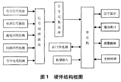
The protection device has the functions of parameter measurement, fault protection, control, remote communication and fault information of the motor when the motor is running.
Storage and query functions. The protection device passes the analog signal of the three-phase voltage, three-phase current, zero-sequence current, etc. of the main circuit through the sensor.
Line detection, through the operation of the single-chip microcomputer, to determine whether there is a fault, if there is a fault, the power supply can be cut off quickly and the alarm will be displayed in time.
Kind of fault information. The system hardware is shown in Figure 1.

As can be seen from Figure 1, the hardware system is mainly composed of the following parts:
(1) The part of the MCU is designed. The main MCU selects the AVR series ATmega128. The AVR is the first one of the 8-bit MCUs.
Positive reduced instruction set (RISC structure) single-chip microcomputer, ATmega128 has good performance, high cost performance and convenient use in AVR single chip microcomputer
Powerful features. 128K Flash; 4K E PROM; 4K SRAM; 53 I/O ports; 34 interrupt sources; 2 16-bit settings
Timer, 2 8-bit timers; own SPI, TwI communication interface; 2 serial communication interfaces; hardware multiplier; 8 PWM; 8 10 bits
A/D channel. These resources within the ATmega128 microcontroller fully meet the design requirements of this system.
(2) The analog sampling processing unit uses a high-performance voltage transformer to collect the phase voltage signal between the three phases, and the through-current current transformer
The current and zero sequence current passing through each phase are collected and converted into an appropriate voltage range by an amplifying circuit, and the signal is subjected to conditioning filtering.
After A/D conversion, enter the microcontroller. The single chip ATmega128 analyzes and calculates the voltage signal to correctly display the current grid voltage value.
Protection and alarm for overvoltage and undervoltage faults; acquisition, calculation and analysis of three-phase current signals to correctly display current power
The grid current value protects and displays the overload, short circuit, and disconnection faults.
(3) The keyboard and display interface are set by the button
Input settings, product information and fault information query, time parameter settings; protection device operating parameters, real-time time and when
The fault information at the time of fault occurrence is Chinese, characters and figures using a 128×64 dot matrix Chinese character graphic type liquid crystal display module LCM12864ZK
Shape display, intuitive and convenient.
(4) Real-time clock unit is produced by DALLAS
The SPI interface clock chip DS1305 acts as a clock circuit for the protector, and realizes the operation of the DS1305RAM through ATmega128.
Set up and read.
(5) The remote communication unit uses the MAX485 chip to realize the remote upper and lower position monitoring functions.
(6) The fault blocking module protection device is designed with a leakage lock function, which is tested before power transmission to avoid the leakage of electricity before the power transmission to the human body and equipment.
(7) Alarm trip unit When a fault is detected, the output unit controls the corresponding relay to realize the trip to cut off the power supply of the motor, and protect the motor with the buzzer alarm.
3 software design
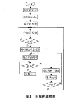
The program of the protection device is written in C language. The main program includes system initialization, boot interface display, pre-closing detection, and keyboard scanning.
Processing, parameter display, fault diagnosis and remote communication. The initialization program includes I/O initialization, timer initialization, interrupt initialization, communication initialization, and the like. The calculation of voltage and current AC is based on the root mean square algorithm. The device is equally spaced in one cycle (20 ms).
By collecting 20 points and performing the root mean square operation in sequence, the effective values ​​of the AC analog signals can be obtained. In order to make people
The eye observation is comfortable, the display interface is refreshed every 2 seconds, and the program determines whether a fault has occurred in real time. If there is a fault, it will immediately trip, indicating
Barrier information (fault sequence number, fault type, fault time) and the fault information is stored in E PROM. The main program flow is shown in Figure 2.

4 Conclusion
The motor intelligent protector is an intelligent, modular and cost-effective motor protection device.
The protection device runs stably, the protection action is reliable, the man-machine interface is simple, and the display information is rich, which has great market application prospects.
SVLEC provide different cable gland , like Plastic cable gland , Metal cable gland , Metal dust cap , EMC cable gland , Nylon cable gland , tube fittings , locking type cable connector .

Cable Glands,Metal Dust Cap,Impact Cable Gland,Nylon Cable Gland
Kunshan SVL Electric Co.,Ltd , https://www.svlelectric.com