Large-scale LED display systems have been widely used in a variety of indoor and outdoor applications, but because of the multi-machine system, the system cost and hardware and software design complexity are improved. When a multi-machine system is working, it is essentially equivalent to a computer system with a high bus width. The technical difficulties are as follows:
â—† The number of pixels on a large LED display is tens of thousands. As the display area increases, the circuit structure increases.
◆ In order to ensure a certain display quality, the frame rate should be above 30 frames/s. For a 512×252 monochrome LED screen, the data transfer rate per second is at least 480 KB. For high color screens and high display quality, the data transfer volume will increase by an integral multiple.
â—† When the LED screen is located outdoors, the communication between the upper and lower machines may be more than 100 meters or even more, requiring fast and reliable communication.
In view of the above two technical difficulties, in order to be able to use a single CPU system instead of a multi-machine system to control a large LED display system, the response strategies adopted are as follows:
â—†The large lED screen is composed of universal display modules, and the display module has good versatility and embeddability.
â—†Using 16-bit parallel bus data transmission mode, to display the display module at the corresponding position, the column latch unit on the module can be accurately gated, so that the horizontally cascaded LED display module can be regarded as a continuous storage unit.
â—†Using the DMA controller inside the S3C44BOX for data transmission and control, saving the CPU fetching and translating time using the instruction to transfer data and the software overhead such as counting, comparison, and jump accompanying the transmission of the command data, thereby enabling continuous The data transmission is completed in the read and write operations, which improves the speed and efficiency of data transmission.
1 hardware structure and principle
The large LED display system is generally divided into two parts: the main control board and the display drive module.
1.1 display module
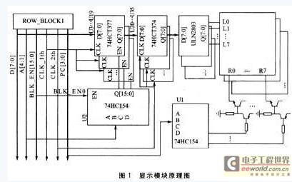
Nowadays, the large-scale LED display system uses the human eye visual features to adopt the progressive scan and the column drive method to save hardware expenses. The system adopts 1/16 progressive scan mode, so the whole large LED screen is divided into 16 rows of the same name. The schematic diagram of the display module is shown in Figure 1.

Each display module is a 64×32 small dot matrix screen, which is divided into two parts, 16 lines above and below, and each part has 8 sets of column data latches. The upper and lower parts are multiplexed with one 4-16 decoder U1, the strobe drives 1/16 progressive scan display, and 16 sets of column drive latches are required to latch the column display data. When parallel bus data transmission is used, a 4-16 decoder U2 strobe enable column latch is required. In dot matrix refresh, a two-stage latch is required to latch the column display data, otherwise display smearing will occur. The data being displayed in this time exists in the second-stage latch, and the main control board writes a row of data to be displayed on the first-stage latch of the screen to perform column data refreshing, and when the data to be displayed in the next row is transmitted, together It is latched to the second stage latch output and gated to drive the next line of display. In the parallel bus mode, the secondary latch is still more economical than the serial transmission of data and then converted to parallel output.
When the display module and the module are horizontally cascaded, the idea of ​​misalignment cascade is used to make it have good versatility and embeddability. As shown in Figure 1, the gate line is misplaced once every level and passed to the next stage, always making the first gate line BLK_EN0 the enable control of the first stage column latch decoder. Line, so that n gate lines can sequentially strobe the n-level horizontal cascading module. In this way, the same display module can be arbitrarily combined into a horizontally cascaded strip screen.
Using the misalignment cascading idea, the decoder U2 of the first stage latch on the horizontally cascaded display module can be sequentially strobed, and the decoder can sequentially strobe the first stage column data latches, such that The first stage column data latch on the horizontal cascading screen can be viewed as a contiguous memory location, which is the basis for DMA parallel data transfer control.
1.2 Interface design of main control circuit and LED screen
This display system uses S3C44BOX based on ARM7TDMI core with internal DMA controller as the main controller, so that it works in ARM state and uses 16-bit bus. Since the LED screen is regarded as a continuous storage unit, it is allocated an address space of 0x2000000 to Ox4000000.
The main control circuit and the LED screen interface should be able to achieve the following functions:
â—† Strobe the display module at any position and the first-level column data latch on the module. The dot code to be displayed at the position is accurately latched, and after the first stage column data latch data is refreshed, the refresh data is latched to the second level column data latch and output.
â—† It can control the strobe drive to drive one line of 16 lines of the same name for progressive scan display.
â—† Realize the logic level conversion of the main control chip 3.3 V to the LED screen 5V.
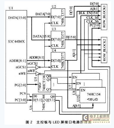
The schematic diagram of the main control board and LED screen interface circuit is shown in Figure 2.

The structure of a large LED screen can be divided into a vertical cascade and a horizontal cascade, which is similar to a three-dimensional array. Suppose a three-dimensional array of LED[i][j][k], where:
i=0,1,2,...,m represents the serial number of the vertical cascade of the LED screen.
j = 0, 1, 2, ..., n represents the serial number of the horizontal cascade of the LED screen.
k=O, 1, 2, ..., 16 represents the sequence number of the 16 first-level column data latches on the display module.
&nbs
p; Because the system uses 16-bit parallel bus data transmission mode, and the LED screen is regarded as a continuous storage unit, use A[4:1] as the first module column data latch decoder on the display module. (U2 in Figure 1) The decoding input is the k variable of the three-dimensional array; using A[8:5] as the coder of the strobe horizontal cascading display module (U7 in Figure 2), the decoding input is The j variable of the three-dimensional array; due to the good flexibility of the LED screen, and the technical requirement of the DMA transmission data requiring the dot matrix code storage sequence, the vertical cascade strobe does not satisfy the condition of using the address bus decoding strobe. Therefore, the PG[2:0] of S3C44BOX is used as the decoding input of the vertical cascaded strobe decoder, that is, the i variable of the three-dimensional array.
Since the status on the address and data bus is constantly changing, the address and data signals should be latched while the LED screen is being written. The U2, U3, and U4 latches the address for the LED write operation on the main control board. And the state of the data bus. The first screen of the LED screen is allocated to Ox2000000. When writing to it, the nGCS1 and nWE pins of the S3C44BOX will have an active low level of programmable control delay. nGCS1 is enabled by a non-gate for U2, U3, and U4 latching control signals to ensure that the signals on the address and data buses are latched only when accessed by the LED screen. The nWE is enabled by a non-gate for the first stage column data latch (U3~U19 in Figure 1) to enable the control signal to ensure that the refresh data is only present when the column data latches its input. Latch. The PCI0 of S3C44BOX is used as the latch enable control signal line for all the second-stage latches of the screen (U20~U35 in Figure 1); the PC[3:O] of S3C44BOX is the 16-row drive decoder (U1 in Figure 1) The decoding input. Since only the main control board needs to control the LED screen output during data transmission, no signal feedback is needed, so the interface circuit adopts the inexpensive 5V power supply HCT circuit chip solution, which can meet the logic level of the main control chip 3.3V to the LED screen 5V. Conversion.
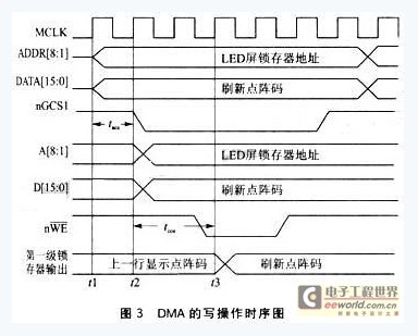
When transferring data in DMA, it is more concerned with the write operation of DMA. The timing is shown in Figure 3. At the time t1, the DMA write operation starts, and the address and refresh data of the corresponding position of the LED screen appear on the address and data bus; at the time t2, the nGCS1 pin has an active low level, and the data on the address and data bus is latched to U2 to U4 and output. At t3, the nWE pin has an active low level, and the output data of U2~U4 is latched to the first-stage column data latch of the screen and output. In this way, the main controller completes the refresh of the column data.

2 software design
2.1 LED screen display program design
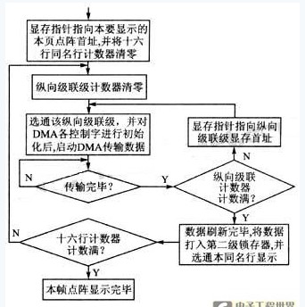
Due to the use of S3C4480X internal DMA controller for data transmission and control, the display program is greatly simplified, the program flow is shown in Figure 4. The transmission of the dot matrix code is all completed by the DMA controller. It is only necessary to assign the first address of the dot matrix code, the first address of the LED screen and the value of the transmitted data amount to the corresponding control words before starting the DMA data transmission, and then start the DMA. Just operate. After all the dot-matrix code transmissions of the same name are completed, the refreshed data is latched to the output of the second-level column data latch, and the line of the same name is displayed. This way, after displaying 16 lines of the same name in a loop, a dot matrix display is completed.

2.2 Dot matrix sorting
Packages For Wireless Communications,High Power Red Lasers,High Power Diode Lasers,High Power Pulsed Lasers
Shaanxi Xinlong Metal Electro-mechanical Co., Ltd. , https://www.cnxlalloys.com