Crystal oscillator direct frequency modulation circuit?
Today, the electronic enthusiasts network together with everyone to study the direct frequency modulation circuit of the crystal oscillator:
The center frequency stability of the direct frequency modulation circuit of the varactor diode (to the LC oscillator) is poor. In order to obtain high-stability FM signals, frequency stabilization measures must be taken, such as adding automatic frequency trimming circuits or phase-locked loops (discussed in Chapter 8). Another simple method of frequency stabilization is to directly tune the frequency of the crystal oscillator. 
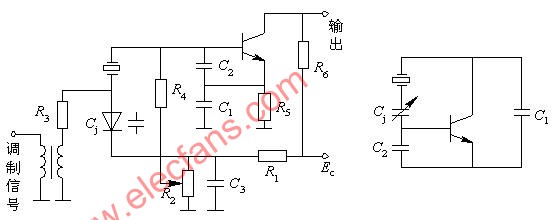
(A) Actual circuit; (b) AC equivalent circuit
a) It is the direct frequency modulation circuit of the varactor diode to the crystal oscillator. Figure (b) is its AC equivalent circuit. It can be seen from the figure that this circuit is a parallel crystal Pierce circuit, and its stability is higher than the Miller circuit. Among them, the varactor diode is equivalent to the fine-tuning capacitor in the crystal oscillator, and its series equivalent capacitance with C1 and C2 is used as the load capacitance CL of the quartz resonator. The oscillation frequency of this circuit is:

Features: Quartz crystals work in the inductive area. The oscillation frequency is between the series oscillation frequency and the parallel oscillation frequency of the crystal. The relative frequency deviation is very narrow, only 10-3 ~ 10-4.
The method of expanding the frequency deviation: A. Parallel small inductance at both ends of the crystal, this method is simple and effective, but the expansion range is limited, and the center frequency stability will be reduced;
B. Impedance transformation using π-type network;
C. Add a method of multiple frequency multiplication and mixing at the output of the FM oscillator. This method not only meets the requirements of carrier frequency, but also increases the frequency deviation.
As the chip carrier for integrated circuits, lead frames are required in the vast majority of semiconductor blocks and are an important basic material in the electronic information industry. The integrated circuits lead frame maximizes chip performance, such as the heat-diffusing function, and enables it to be operated for long periods of time.
High Precision Etching IC Lead Frame is widely used in emerging products such as artificial intelligence, Internet of Things, smart manufacturing and new energy vehicles. The raw material use for IC Lead Frame are C192 or C194 Copper, which the material C192 has better conductivity. The production of smooth IC lead frames by metal etching process can achieve higher precision, for example, we can produce multi-pin (more than 100 pins) products of multi-pin IC lead frame, and can also produce ultra-thin products, such as etched 0.125mm thickness IC lead frame. Moreover, we can guarantee that our copper IC lead frame or half etching lead frame have uniform arrangement, straight etching line and smooth and delicate finishes.
Integrated Circuits Lead Frame,High Precision Etching IC Lead Frame,0.125mm Thickness IC Lead Frame, Multi-pin IC Lead Frame
SHAOXING HUALI ELECTRONICS CO., LTD. , https://www.cnsxhuali.com