Circuit breaker protection mainly includes: breaker failure protection, automatic reclosing, charging protection, dead zone protection, three-phase inconsistent protection and instantaneous follow-up. This article focuses on circuit breaker protection in 3/2 wiring.
First, the configuration of the circuit breaker protection device
Generally, in the double busbar and single busbar wiring mode, when the transmission line protection is to issue a trip command, only one circuit breaker at the local end of the line is jumped, and the reclosing is naturally only coincident with this one circuit breaker, so the reclosing is reasonable according to the protection configuration.
In the 3/2 wiring mode, failure protection, automatic reclosing, three-phase inconsistency protection, dead zone protection and charging protection are implemented in one device. This device is called circuit breaker protection.
Second, the breaker failure protection
Breaker failure protection means that when the relay protection action of the faulty electrical equipment issues a trip command and the circuit breaker refuses to move, the protection action information of the faulty device and the current information of the rejected circuit breaker constitute a discriminating failure of the circuit breaker, which can be compared Short time limit cut off other related circuit breakers in the same plant station to minimize the power outage range, thus ensuring stable operation of the entire power grid, avoiding serious burning of faulty components such as generators and transformers and collapse of the power grid.
Circuit breaker failure protection is generally configured on circuit breakers of 220kV and above, and some important 110kV circuit breakers are also equipped with malfunctioning functions. The following detailed analysis: breaker failure protection in 3/2 wiring mode.
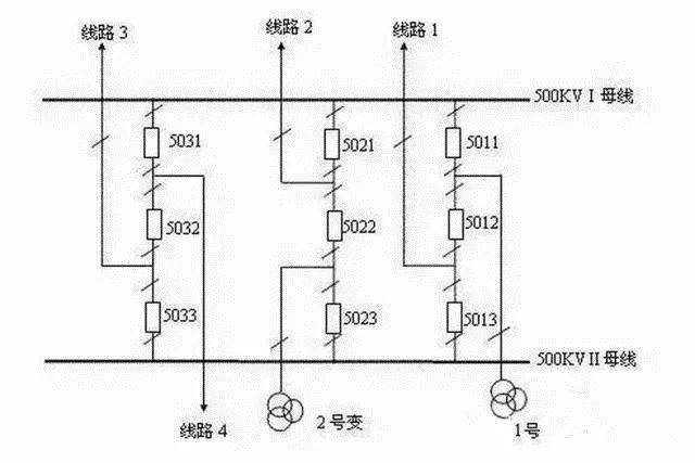
As shown in Figure 1, in the 3/2 wiring mode, if a short circuit occurs on line 2, the line protection trips the 5021 and 5022 circuit breakers. If the 5021 circuit breaker fails, in order to extinguish the arc at the short circuit point, the failure protection of the 5021 circuit breaker should jump off all the circuit breakers on the 500kVI mother circuit (5011, 5031 circuit breaker in the figure).

Fig.1 Schematic diagram of 3/2 wiring mode of 500kV substation
If a short circuit occurs on the 500kVI bus, the busbar protection action jumps all circuit breakers on the bus. If the 5021 breaker fails, the failure of the 5021 breaker should trip the 5022 breaker and send a remote trip command to jump the breaker on the opposite side of the line 2. (If the connecting component is a transformer, jump off the circuit breaker on each side of the transformer)
Therefore, after the failure protection of the circuit breaker, all circuit breakers and medium circuit breakers on the busbar where the circuit breaker is located should be tripped and the remote trip function function should be triggered to jump off the line side circuit breaker connected to the side circuit breaker (or each side of the jump transformer) Device).
If a short circuit occurs on line 2, the line protection jumps 5011 and 5021 two circuit breakers. If the 5022 breaker fails, the failure of the 5022 breaker should break the 5023 breaker and send a remote trip command to jump the breaker on the 2nd main transformer so that the short-circuit point can be extinguished.
Therefore, after the failure protection of the circuit breaker, the two side circuit breakers on both sides of the circuit breaker should be tripped, and the remote trip function is activated to jump the line side circuit breaker (or the circuit breaker on each side of the transformer) connected to the medium circuit breaker.

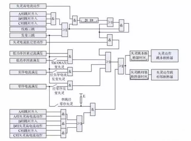
Figure 2 Schematic diagram of failure protection action
If the above-mentioned failure protection does not activate the remote trip function, the backup protection of the line can be used to cut off the opposite side circuit breaker, but the fault removal time will be lengthened. Moreover, the middle breaker failure protection basically has a malfunctioning action to start the remote trip function.
The failure process of the circuit breaker under the double busbar wiring mode will not be described again, and it is simpler than the 3/2 wiring mode.
Third, about automatic reclosing
1. Requirements for automatic reclosing sequence
In Figure 1, if line 2 is short-circuited, line 2's protection action trips 5021 and 5022 breakers, and the reclosing will naturally also close the two breakers. Considering that it is possible to coincide with a permanent fault line, in order to reduce the impact, the two circuit breakers should not coincide at the same time. So there is a sequence of problems that first overlaps.
Is it a front-end circuit breaker or an intermediate circuit breaker?
If the intermediate circuit breaker 5022 is first engaged and coincides with a permanent fault, the line protection then jumps to the 5022 circuit breaker. In case the 5022 circuit breaker fails at this time, the failure of the 5022 intermediate circuit breaker will jump off the 5023 circuit breaker, and will jump far away to open the circuit breaker on each side of the main transformer No. 2 (if the line then jumps to the opposite side circuit breaker), this will Affects the work of the main component (or line) of the connected component No. 2, so the intermediate circuit breaker cannot be overlapped first.
If the front-end circuit breaker 5021 is also superposed on a permanent fault, the line protection will jump to the 5021 circuit breaker. In case the 5021 breaker fails at this time, the 5021 breaker failure protection trips all the circuit breakers on the I bus and sends the circuit breaker on the opposite side of the far jump line 2, the connection components of the line 2 or other components are not affected. .
Therefore, when the line protection trips two circuit breakers, the circuit breaker should be closed first. After the circuit breakers are successfully re-engaged, the circuit breakers are combined. At this time, the circuit breakers must be in good condition. If the circuit breaker overlap is unsuccessful and is combined with the faulty line, the protection will trip the circuit breaker again, and the circuit breaker will no longer coincide.
2. Start and mode setting of reclosing
The reclosing is initiated in two ways: the position does not correspond to the start and the external trip starts. External trip start refers to the line protection action trip command and the reclosing is started at the same time.
o The position does not correspond to the start-up: single-phase stealing start and three-phase stealing start.
o Protection trip start is divided into single-phase trip start and three-phase trip start.
Regarding the setting method of the reclosing, one of the four methods of single-phase reclosing, three-phase reclosing, integrated reclosing and reclosing deactivation can be selected as needed. The reclosing mode can be selected by using the toggle switch on the screen or the control word in the rating list.
3. Reclosing inspection method
Reclosing inspection method: When the three-phase tripping of the line requires three-phase coincidence, the following three methods can be used.
§ ?? Detecting the synchronous mode: the line, the synchronous voltage is greater than 40V, and then the phase difference between the line voltage and the phase voltage of the same name in the synchronous voltage is within the range of the fixed value setting.
§ Check no pressure mode: check the line or synchronous voltage is less than 30V, and the corresponding TV is not broken.
§ No verification method: no inspection is performed, and the closing command is issued when the time is up.
4. About reclosing and reclosing
The first closing circuit breaker is combined with the fault, and the rear closing circuit breaker is no longer closed. In the 3/2 wiring mode, there is a problem of pre-closing and rear-closing for the reclosing of the side breaker and the middle breaker. We mentioned it before when we talked about the failure. The following is a brief description:
The first closing and closing can send a closing pulse with a short delay. When the first closing and closing is started, the output switch contact is used as the "locking first" switching input of the rear closing and closing.
When the rear recloser receives the message of the "locking first" input contact closure, its reclosing will send a closing pulse after a longer delay. The rear reclosing is only used to send the closing pulse with a long delay when the input of the "locking first" is input.

Figure 3: First reclosing and rear reclosing
First reclosing:
"Population first" - soft pressure plate, hard pressure plate
Short delay (reclosing setting time, about 0.7s)
?? Rear combined closing:
"locking first"
"post-fixed" control word
Long delay (reclosing setting time + post-coincidence delay, about 1.4s)
Fourth, charging protection
When the components such as the bus bar are charged by the circuit breaker in which the device is placed to be combined with the faulty component, charging protection is provided as protection in this case. The charging protection consists of two-stage two-phase phase overcurrent and one zero-sequence overcurrent composed of phases, and the current is taken from the TA of the circuit breaker.
When the charging protection is input, the phase current component of the corresponding segment acts after the corresponding setting delay, and the charging protection action exits the circuit breaker. After the charging protection action, the start failure protection, and then the other circuit breakers are skipped by the failure protection delay.

Figure 4 charging protection action schematic
In addition, failure protection, dead zone protection, inconsistent protection, and charging protection actions are all closed and closed. Charging protection is only applied when the line (transformer) is charging, and exits immediately after charging is normal.
Five, dead zone protection
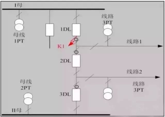
Cause of dead zone: When a short circuit occurs between the circuit breaker and the current transformer, in many cases the fault cannot be removed after the protection action.
Brief description of the dead zone: The following fault at K1 is in the I busbar protection zone, but after the I mother protection action trips all the I female circuit breakers containing 1DL, the fault point is still in the system, and such fault is the dead zone fault. .
The meaning of the configuration of the dead zone: Considering the dead zone faults occurring in the station, the current is generally large, and the impact on the system is also large. Although the fault is reliably removed, the failure protection action generally takes a long delay, so Set dead zone protection faster than failure protection.

Figure 5 Schematic diagram of the dead zone
Input for dead zone protection: On the basis of the failure protection input, the dead zone protection control word also puts into the dead zone protection function.
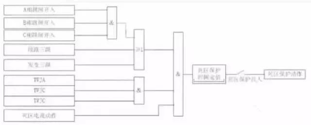
Dead zone protection action: three-phase trip signal (for example: three-hop change, three-hop line, or three phase-breaking trips of A, B, C) + three-phase jump (TWJ signal) + dead zone current action The dead zone protection is activated by the dead zone delay.
The exit of the dead zone protection: consistent with the exit of the breaker failure protection, that is, which circuit breakers are tripped by the faulty exit of the circuit breaker, then which circuit breakers are jumped at the exit of the circuit breaker dead zone.
This is the reason why the dead zone protection is attached to the failure protection platen. The dead zone protection can also be understood as an alternative (different criteria, different delays) failure protection.

Figure 6 charging protection action logic diagram
Six, three-phase inconsistent protection
The origin of three-phase inconsistency: Circuit breakers with phase-separated operation, due to equipment quality and operation, etc., three-phase circuit breakers may be inconsistent in operation, resulting in only one phase or two phases jumping out, which is in a non-full phase abnormal state.
Three-phase inconsistency hazard: When the system is in non-full-phase operation state, the negative sequence, zero sequence and other components appearing in the system have certain harm to the electrical equipment, and also affect the correct operation of the system protection device, so the power system is not allowed to be long. Time is not full phase operation.
If the line overlap is unsuccessful, there will be no other protection to eliminate the fault when the system enters non-full-phase operation. Therefore, the phase-locked circuit breaker is installed with non-full-phase protection (three-phase inconsistent protection), when the system is incomplete When the phase reaches a certain time, the other phases are skipped.
The realization of three-phase inconsistency: the protection function of eliminating the abnormal state of three-phase inconsistency, in the high-voltage or ultra-high-voltage class system, generally implemented in the circuit breaker body, but also implemented in the circuit breaker protection (or line protection) in).
Inconsistent protection in the circuit breaker body, the national network 18 items of countermeasures: 220kV and above voltage circuit breakers should be equipped with three-phase position inconsistency protection of the circuit breaker body.
After the single-phase trip of the circuit breaker, if the reclosing action occurs, the circuit breaker does not overlap successfully due to pressure, mechanical, secondary circuit, etc., and must jump three-phase within 2-2.5s and no longer overlap. Ensure the safety of the system.

Figure 7 Three-phase inconsistent protection logic diagram
When there is no three-phase inconsistent protection in the circuit breaker, an independent three-phase inconsistent protection device can be installed. Independent three-phase inconsistent protection In addition to using the circuit breaker auxiliary contact or position contact to form a starting circuit that judges three-phase inconsistency, a zero-sequence current and a negative-sequence current blocking circuit can be used to improve the reliability of the circuit.
Input of three-phase inconsistent protection: When the three-phase inconsistent protection soft plate and hard plate are both input (control word), the three-phase inconsistent protection function works.
Three-phase inconsistent start: three-phase jump open inconsistency + jump phase no flow.
Three-phase inconsistent protection action: Inconsistent zero-sequence open control word input, inconsistent start through inconsistent zero-sequence current criterion action, and then jump three-phase circuit breaker circuit breaker through inconsistent delay. The inconsistency is controlled by the negative sequence open control word input, the inconsistent start is caused by the inconsistent negative sequence current criterion, and then the three-phase circuit breaker is tripped by the inconsistent delay. When the above two control words are exited, the three-phase inconsistency starts after the inconsistency delay exit jumper circuit breaker three-phase.
The three-phase inconsistent protection action does not start failure and locks the reclosing.
Blocking of three-phase inconsistent protection: The circuit breaker is in a three-phase inconsistent state for 12 seconds, the position is inconsistent alarm, and the three-phase inconsistent protection is blocked.
The principle of setting the time relay of three-phase inconsistent protection: the three-phase inconsistent protection delay setting value of the relay protection device should be able to avoid the action time of the reclosing.
Seven, instantaneous jump
The loop is determined by the user whether or not to invest. The instantaneous follow-up jump is divided into: single-phase and jump, two-phase trip and three-phase and three-phase follow-up. After the three loops exit, the circuit breaker is jumped once again, and the above three loops can only issue a trip command when the starting component operates.
· Single-phase and jump: ?? Receive the line protection Ta, Tb, Tc single-phase trip signal, and the high-value current component of the corresponding phase acts, instantaneous phase split trip.
· Two-phase tripping and three-phase tripping: Receive and receive only the two-phase trip signal from the line protection, and the high-valued current component of any phase operates, and the three-phase is tripped with a delay of 15ms.
· Three-phase follow-up: A three-phase trip signal is received, and the high-valued current component of any phase operates and the instantaneous three-phase trips the exit.
Eight, AC voltage disconnection judgment
The criterion for the disconnection of AC voltage disconnection is: protection does not start, and the three-phase voltage vector sum is greater than 12V, and the TV short-circuit abnormal signal is delayed by 1.25s. When the TV is disconnected, the low-power factor component will be withdrawn, and the simultaneous detection and detection of the pressureless coincidence function will be withdrawn, and other functions are normal. When the three-phase line voltage returns to normal for 10s, it will automatically resume normal operation.
Nine, trip position abnormal alarm
When the TWJ operates and the phase line has current, or the three-phase TWJ position is inconsistent, the TWJ is abnormally reported by the 10S delay.
Dongguan Deli Plastic Co.,Ltd is a manufacturer specialized in the research, development ,plastic injection mould and making mass production with well-equipped facilities and strong technical force.
Our products are extensively used in household industry/electronic industry/automobile industry/building industry and other industries.
We have rich experience on one-stop solution, provide various services from new product design,prototype,mold making,mass production,assembly and logistics. The most important advantage is we have our own R&D team to help clients to turn ideas into actual parts. All of these engineers and designers have over 15 years experience in these plastic products fields.
We have a strict quality control system, an excellent management team and also a dedicated sales force, enable us to fulfill our commitment in high quality products and outstanding services.
If you are looking for a trustworthy supplier of customized items, please do not hesitate to contact us. We are always striving to establish a win-win partnership with customers from all over the world and help our partners to stay one step in front of your competitors.
usb mini Fan,usb rechagerable Fan,usb portable Fan
Dongguan Yuhua Electronic Plastic Technology Co.,Ltd , https://www.yuhuaportablefan.com