1 Introduction Inverter driven asynchronous motor speed regulation. After the asynchronous motor is determined, the inverter should normally be selected according to the rated current of the asynchronous motor, or the inverter should be selected according to the current value (maximum value) in the actual operation of the asynchronous motor. When the operation mode is different, the calculation method and selection method of the inverter capacity are different, and the conditions that the inverter should meet are also different. When the inverter capacity is selected, the rated current of the inverter is a critical quantity, and the capacity of the inverter should be selected according to the maximum operating current that may occur during operation. There are several ways to operate the inverter.
2 Calculation of the inverter capacity required for continuous operation Since the inverter transmits the pulse current to the motor, the pulsation value is larger than the current at the power frequency supply, so the appropriate capacity of the inverter must be left. At this point, the frequency converter should meet the following three conditions: 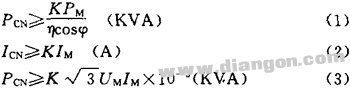 Screen.width-461) window.open("/edit/UploadFile/2009418145123726.jpg");">
Where: PM, η, cosφ, UM, IM are motor output power, efficiency (take 0.85), power factor (take 0.75), voltage (V), current (A).
K: correction coefficient of current waveform (PWM method is taken from 1.05 to 1.1)
PCN: rated capacity of the inverter (KVA)
ICN: rated current of the inverter (A)
In the case where the IM selects the inverter according to the maximum current in the actual operation of the motor, the capacity of the inverter can be appropriately reduced.
3 Selection of inverter capacity during acceleration and deceleration The maximum output torque of the inverter is determined by the maximum output current of the inverter. Under normal circumstances, for short-term acceleration and deceleration, the inverter is allowed to reach 130% to 150% of the rated output current (depending on the inverter capacity), so the output torque during short-time acceleration and deceleration can also be increased; Conversely, if only a small acceleration/deceleration torque is required, the capacity of the selected inverter can also be reduced. Due to the pulsation of the current, the maximum output current of the inverter should be reduced by 10% at this time.
4 When the frequency is frequently accelerated or decelerated, the inverter capacity is selected according to the current values ​​in various operating states such as acceleration, constant speed, and deceleration.
I1CN=[(I1t1+I2t2+...+I5t5)/(t1+t2+...t5)]K0
Where: I1CN: rated output current of the inverter (A)
I1, I2, ... I5: Average current in each operating state (A)
T1, t2, ... t5: time K0 in each operating state: safety factor (1.2 when running frequently, 1.1 under other conditions)
5 One inverter drives multiple motors, and multiple motors run in parallel, that is, when one inverter is used to make multiple motors run in parallel, after a small number of motors start to start, they are added to other motors. In this case, the voltage and frequency of the inverter have risen at this time, and the additional input motor will generate a large starting current. Therefore, the inverter capacity needs to be larger than that at the same time.
Calculate the capacity of the inverter by taking the short-time overload capacity of the inverter as 150% and 1min as an example. If the motor acceleration time is within 1min, the following two types should be satisfied. 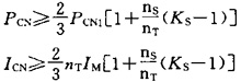 Screen.width-461) window.open("/edit/UploadFile/2009418145123871.jpg");">
If the motor accelerates above 1mn 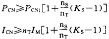 Screen.width-461) window.open("/edit/UploadFile/2009418145123675.jpg");">
Where: nT: number of parallel motors ns: number of simultaneous starts PCN1: continuous capacity (KVA) PCN1=KPMnT/ηcos
PM: Motor output power η: efficiency of the motor (approximately 0.85)
Cosφ: the power factor of the motor (usually 0.75)
Ks: motor starting current / motor rated current IM: motor rated current K: current waveform positive coefficient (PWM method takes 1.05 ~ 1.10)
PCN: Inverter Capacity (KVA)
ICN: rated current of the inverter (A)
The inverter drives multiple motors, but one of them may be connected to the inverter at any time or exit at any time. The rated output current of the inverter can be calculated as follows: 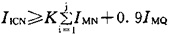 Screen.width-461) window.open("/edit/UploadFile/2009418145124766.jpg");">
Where: IICN: rated output current of the inverter (A)
IMN: Motor rated input current (A)
IMQ: Starting current of the largest motor (A)
K: Safety factor, generally taken from 1.05 to 1.10
J: The number of remaining motor units 6 The calculation of the inverter capacity required when the motor is directly started Generally, the starting current of the three-phase asynchronous motor is directly 5 to 7 times of the rated current when starting with the power frequency, and is directly for the motor with the motor power less than 10 kW. When starting, the inverter can be selected as follows.
I1CN≥IK/Kg
Where: IK: stall current (A) when the motor starts at rated voltage and rated frequency;
Kg: Allowable overload multiple of the inverter Kg=1.3~1.5
During operation, if the motor current changes irregularly, it is not easy to obtain the running characteristic curve at this time. At this time, the current limit of the motor when outputting the maximum torque can be selected within the rated output current of the inverter.
7 Inverter capacity calculation when starting the large inertia load The overload capacity of the inverter is usually 125%, 60s or 150%, 60s. When an overload capacity exceeding this value is required, the capacity of the inverter must be increased. In this case, the capacity of the inverter is generally calculated as follows: 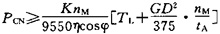 Screen.width-461) window.open("/edit/UploadFile/2009418145124370.jpg");">
Where: GD2: The moment of inertia converted to the motor shaft (N·m2)
TL: load torque (N·m)
η, cosφ, nM are the efficiency of the motor (take 0.85), power factor (take 0.75), rated speed (r/min).
tA: Motor acceleration time (s) is determined by load requirement K: correction coefficient of current waveform (PWM mode is taken from 1.05 to 1.10)
PCN: rated capacity of the inverter (KVA)
8 When the light load motor is selected, the actual load of the motor is lower than the rated output power of the motor. It is considered that the inverter capacity can be selected to match the actual load. However, for the general-purpose inverter, even if the actual load is small, the use ratio is lower than the rated motor. The frequency converter with small capacity of the inverter is not ideal, which is mainly due to the following reasons;
1) When the motor is idling, it also flows through the excitation current of 30% to 50% of the rated current.
2) The starting current flowing during starting corresponds to the voltage and frequency applied by the motor. Regardless of the load torque, if the inverter capacity is small and the current exceeds the overcurrent capacity, it will not start.
3) If the motor capacity is large, the leakage reactance percentage of the motor based on the inverter capacity becomes smaller, and the pulsation of the inverter output current increases, so the overcurrent protection capacity operates and often cannot operate.
4) When the motor is started with a general-purpose inverter, its starting torque is mostly smaller than that of the power-frequency power supply. It may not start depending on the starting torque characteristics of the load. In addition, the torque in the low-speed running area tends to decrease from the rated torque. When the selected inverter and motor cannot meet the required starting torque and low-speed range torque of the load, the capacity of the inverter and the motor are also Need to increase.
The above describes the capacity calculation and selection method of the inverter under several different conditions. When selecting the capacity, it is necessary to make full use of the overload capacity of the inverter, and not to overheat the device when the load is running. Some manufacturers (such as ABB) also have deterministic device quota software that can determine the output rating of the device as long as the user presents a clear load map.
Our Lithium Battery includes 5G Base Station Backup Power System,like 48V 100Ah/150Ah/200Ah Lithium Battery. 3.2V Prismatic cells,like 3.2V 50Ah/105Ah/202Ah Lithium Battery. And Lithium Ion Pouch Cells, including 3.2V 12-30Ah.
Lifepo4 Battery,Lifepo4 Lithium Ion Battery,Lifepo4 48V 100Ah Lithium Ion Battery,Lithium Ion Battery For Solar 100Ah
Jiangsu Zhitai New Energy Technology Co.,Ltd , https://www.zhitainewenergy.com