The instrumentation amplifier reference input is generally considered to be high impedance because it is an input port. Therefore, you may connect a high-impedance source, such as a resistor divider, to the reference pin of the instrumentation amplifier.
However, for some types of instrumentation amplifiers, this can cause serious errors.
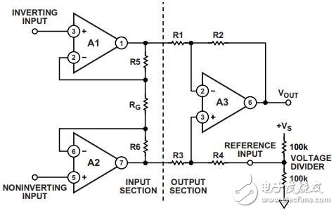
For example, a popular instrumentation amplifier design uses a three-operational amplifier with a connection method as shown in Figure 1. Total signal gain is

among them:

If driven by a low impedance source, the gain at the reference input is unity gain. In this case, however, the reference pin of the instrumentation amplifier is directly connected to a simple voltage divider. This destroys the symmetry of the subtraction circuit and the distribution ratio of the voltage divider circuit, and reduces the common mode rejection capability and gain precision of the instrumentation amplifier.
However, in some cases, R4 is adjustable, thus reducing its resistance by a factor equal to the parallel value of the divider resistor (50 kΩ in this example). At this point, the circuit behaves as if a low-impedance voltage source equivalent to half the supply voltage is connected to R4, which holds the original value. In addition, the accuracy of the subtractor can be maintained.
Figure 1. Improper use of a simple voltage divider to directly drive the reference pin of a three-op amp structure instrumentation amplifier |
This method cannot be used if the instrumentation amplifier is in a single-chip package (IC). Another consideration is that the temperature coefficient of the divider resistor should also be able to track R4 and other resistors in the subtraction circuit. Finally, this approach eliminates the possibility of adjusting the reference voltage. On the other hand, if an attempt is made to reduce the additional resistance by using a small resistance value in the voltage divider, the power dissipation current is increased, thereby increasing the power consumption of the circuit. This is not a good design method.
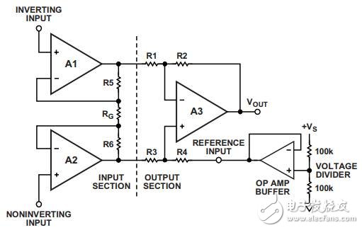
A better solution is shown in Figure 2, which uses a low-power op amp buffer between the voltage divider and the instrumentation amplifier reference input. This approach eliminates impedance matching and temperature tracking issues and allows for easy adjustment of the reference voltage.
Figure 2. Using the low-impedance output of an op amp to drive the reference pin of an instrumentation amplifier |
After reading this article, is the method for providing a true reference voltage for the instrumentation amplifier?
new smart watch,sport smart watch,smart watch supplies,phone smart watch for Iphone
Shenzhen Konchang Electronic Technology Co.,Ltd , https://www.konchangs.com

