When the high-frequency signal is transmitted, the signal wavelength is relatively short with respect to the transmission line, and the signal forms a reflected wave at the end of the transmission line, which interferes with the original signal. Therefore, it is necessary to add a terminating resistor at the end of the transmission line so that the signal does not reflect after reaching the end of the transmission line. It is not used for low frequency signals. In the long-line signal transmission, in order to avoid signal reflection and echo, it is also necessary to access the terminal matching resistor at the receiving end.
Second, the role of terminal resistance in communicationAnother problem that needs to be solved in the RS485 networking process is the terminal load resistance problem. The whole network can work well without the terminal load resistance when the device has a short distance, but the performance will decrease as the distance increases. In theory, when sampling at the midpoint of each received data signal, the match can be ignored as long as the reflected signal decays sufficiently low at the beginning of the sampling. But this is actually difficult to grasp. There is an article in American MAXIM that mentions an empirical principle that can be used to determine what kind of data rate and cable length need to be matched: when the signal conversion time (rise or fall time) No more matching is possible when more than three times the time required for the electrical signal to travel unidirectionally along the bus.
Generally, the terminal matching adopts the terminating resistance method. RS-485 should be connected to the terminating resistor at the beginning and the end of the bus cable. The terminating resistor takes 120Ω in the RS-485 network. A resistor equivalent to the characteristic impedance of a cable, since most twisted pair cables have a characteristic impedance of approximately 100 to 120 Ω. This matching method is simple and effective, but has a disadvantage. The matching resistor consumes a large amount of power, and is not suitable for a system with strict power consumption limitation. Another way to compare power savings is RC matching. Using a capacitor C to block the DC component can save most of the power. However, the value of capacitor C is a difficult point, and a compromise between power consumption and matching quality is required. There is also a diode matching method. Although this scheme does not achieve true "matching", it can quickly attenuate the reflected signal by the clamping action of the diode to achieve the purpose of improving the signal quality, and the energy saving effect is remarkable.
Under normal circumstances, it is not necessary to increase the terminating resistor. Only when the 485 communication distance exceeds 300 meters, the terminating resistor should be added at the beginning and end of the 485 communication.

The role of the terminating resistor in communication is to eliminate signal reflections in the communication cable. However, during communication, there are two reasons for signal reflection: impedance discontinuity and impedance mismatch.
1. Impedance discontinuity: The signal suddenly encounters a small or no cable impedance at the end of the transmission line, and the signal will cause reflection at this place. The principle of such signal reflection is similar to the reflection of light from one medium into another. To eliminate this reflection, it is necessary to connect a terminating resistor of the same magnitude as the characteristic impedance of the cable at the end of the cable to make the impedance of the cable continuous. Since the transmission of the signal on the cable is bidirectional, a similarly sized termination resistor can be bridged across the other end of the communication cable.
2. Impedance Mismatch: Another cause of signal reflection is the impedance mismatch between the data transceiver and the transmission cable. In high-frequency circuits, when the frequency of the signal is high, the wavelength of the signal is very short. When the wavelength is short compared to the length of the transmission line, the superposition of the reflected signal on the original signal will change the shape of the original signal. If the characteristic impedance of the transmission line does not match the load impedance, a reflection will occur at the load end. The reflection caused by this reason is mainly manifested in the fact that when the communication line is in the idle mode, the entire network data is confusing.
To reduce the effect of reflected signals on communication lines, noise suppression and biasing resistors are often used. In practical applications, for relatively small reflected signals, for the sake of simplicity and convenience, a method of applying a bias resistor is often employed.
Additional instructions:
1. RS-485 requires two termination resistors, connected at both ends of the transmission bus, and its resistance requirement is equal to the characteristic impedance of the transmission cable. In the short-distance transmission, there is no need to terminate the resistor, that is, generally no need to terminate the resistor below 300 meters.
2. In order to suppress interference, the RS485 bus often accesses a 120 ohm resistor after the last device (ie, as described above).
3. The common mode output voltage of RS-485 and RS-422 is different. RS-485 common mode output voltage is between -7V and +12V, RS-422 is between -7V and +7V, RS-485 receiver minimum input impedance is 12KΩ; RS-422 is 4kΩ; RS-485 meets all RS-422 specification, so RS-485 drivers can be used in RS-422 networks.
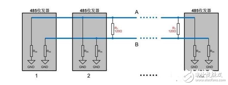
In the field construction of the 485 bus, when the transmission distance of the 485 bus exceeds a certain length, the anti-interference ability of the 485 bus will decrease. In this case, it is necessary to connect 120 ohms at both ends of the 485 bus. The terminal is matched with a resistor to ensure the stability of the 485 bus.
The correct connection of the terminal matching resistors is to connect a 120 ohm terminating resistor on each end of the 485 bus, and the resistor is connected between the positive and negative of the 485 bus. As shown:
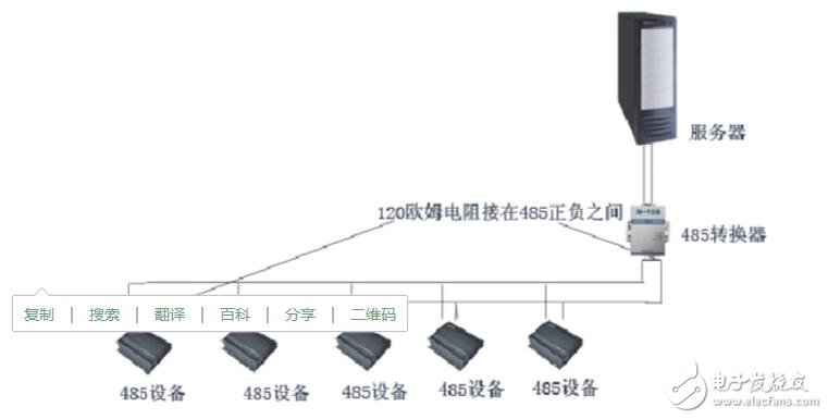
The figure above shows the connection of the terminal matching resistor when using a 485 to 232 converter. 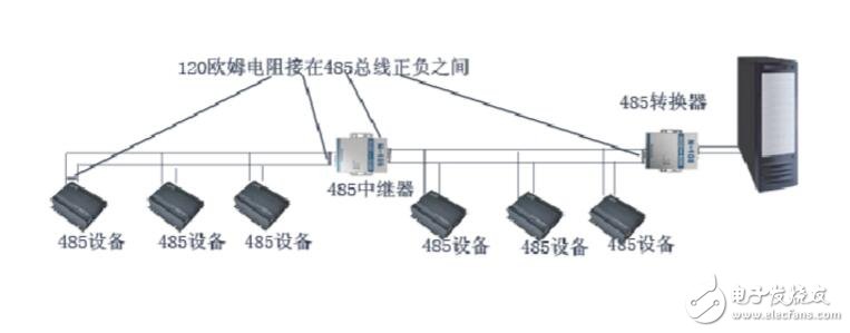
The figure above shows the connection of the terminal matching resistor when the 485 repeater is added. 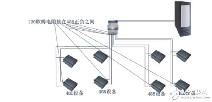
The figure above shows the connection of the termination matching resistor when using a 485 hub.
The off grid inverter is a device that transforms DC power from battery to standard AC power for electronics. Saintish Pure Sine Wave Inverters comes from 300W to 6000W for 12V, 24V or 48V to 110V/230V.
Its output waveform is same as the AC power waveform of mains power grid which delivers a smoothly-varying sine wave for sensitive electronics provided by the electric utility.
A pure sine wave inverter is better than modified sine wave inverter, many off-grid systems require pure sine wave inverters to power everyday electronics, protecting appliance life and no electromagnetic pollution. It is capable of producing cleaner, smoother, quieter and reliable power.
The remote control is available for pure sine wave inverters. There is built-in USB port, install the remote switch on a control panel for very convenient operation.
There are widely application for off grid pure sine wave inverters. Like Solar system, RV, Caravan, Camper, Yatch, household, farm, etc. To choose the right off grid inverter, the types of loads will be very important factors.
Off Grid Pure Sine Wave Inverter, Solar Invert Mppt, 12V Off Grid Inverter, 48V3000W Off Grid Inverter
Hangzhou Saintish Technology Co.,Ltd. , https://www.saintishtech.com