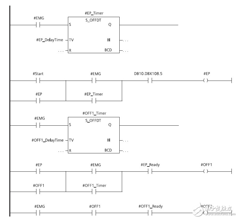
The timing diagram is a time-order diagram that describes the working process of the device and is a graph for visually analyzing the working process of the device. For example, triggers, timers, counters, etc. in electronic technology use timing diagrams to describe their working principle. In the plc sequential control design method, the ladder program is often drawn first, then the flow chart is designed according to the timing diagram, and then the ladder program is programmed according to the flow chart.
First, plc timing diagram programming method:
The timing diagram programming design method is applicable to the occasion when the state change of each output signal of the PLC has a certain time sequence, and all the actions of the system are required to work in time sequence under the control of the timer. In the program design, according to the timing diagram of each output signal drawn, the time and transition conditions of each state transition are straightened, and the corresponding relationship between the output and the input and the internal contact is found out, and appropriate simplification is performed. In general, the sequential logic design method should be used in conjunction with the empirical method, otherwise the logical relationship may be too complicated.
Programming steps for sequential logic design:
1) According to the control requirements, the number of input and output signals is clearly defined;
2) According to the working process of the system, divide the whole work process into several time segments, find the boundary points between the segments, and clarify the conversion relationship and transition conditions of the output signal state at the demarcation point;
3) Assign an internal auxiliary relay to each time period divided by the drawing. For example, the first time period is coded as M0, the second time period is coded as M1, and so on;
4), the ladder program is written with a timer to make these time periods work in the required order;
   5) Find the working time period corresponding to each output and output it in parallel;
6) Through the simulation debugging, check whether the program meets the control requirements, and further modify the program according to the empirical design method;
4. When several series circuits are connected in parallel, the series circuit with the most contacts should be placed at the top of the ladder diagram. When several parallel circuits are connected in series, the parallel circuit with the most contacts should be placed on the leftmost side of the ladder.
Second, the steps of the experience method:1. After accurately understanding the control requirements, reasonably allocate input and output ports for events in the control system. Select the necessary internal devices such as timers, counters, auxiliary relays, etc.
2. For some outputs with relatively simple control requirements, they can directly write out their working conditions, and complete the relevant ladder branch according to the start-guarantee-stop circuit mode. A slightly more complicated working condition can be assisted by an auxiliary relay.
3. For more complicated control requirements, in order to draw the ladder diagram of each output port with the start-stop-stop circuit mode, it is necessary to correctly analyze the control requirements and determine the key points that constitute the total control requirements.
4. Use the program to express the key points.
5. On the basis of completing the keypoint ladder diagram, the ladder diagram is written for the final output of the system.
Third, when editing the ladder diagram, pay attention to the following points:1. Each branch of the ladder diagram should be drawn from the left to the right with the left bus as the starting point. The front part of each line is the "working condition" composed of the contact group, and the right side is the "work result" expressed by the coil or the function box. After one line is drawn, the next line is drawn from top to bottom until the end of the program.
2. The contacts should be drawn on the horizontal line and cannot be drawn on the vertical branch line.
3. Branches that do not contain contacts should be placed in the vertical direction. Do not put in a horizontal position.
Fourth, the timing logic design example:Control requirements: a fountain has three nozzles of A, B, and C. After pressing the start button, the first A, B, and C are sprayed for 3 seconds and then stopped for 1 second, then A, B, and C are sprayed for 1 second, then A and B, B and C, A and C are sprayed for 2 seconds and then stopped for 1 second. Then repeat the above process, and then cycle back and forth until the parking button is pressed.
Solution: 1), I / O allocation:

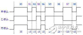
2), draw timing diagram
According to the fountain system control requirements, draw a timing diagram as shown below:

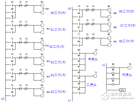
3) Design ladder diagram:

Desktop Phone Holder,Desktop Mobile Phone Holder,Adjustable Desktop Phone Holder,Universal Desktop Cell Phone Holder
Ningbo Luke Automotive Supplies Ltd. , https://www.nbluke.com