Researchers Zhang Lei, Wang Yueqiang and Chen Guoen of State Grid Jiaxing Power Supply Company's Power Dispatching Control Center wrote in the 12th issue of "Electrical Technology" magazine in 2017 that with the rapid development of new energy construction, micro-grid is becoming more and more popular. The control of distributed power supplies plays a huge role.
However, due to the characteristics of the microgrid such as two-way flow, small grid capacity, the protection of the microgrid is difficult. Therefore, it is necessary to develop a grid protection method that is compatible with the characteristics of the microgrid.
Based on the application characteristics of the microgrid, this paper adopts the communication-based microgrid centralized protection scheme, and configures the local protection scheme as a supplement. Finally, the specific microgrid is configured and the ideal protection effect is obtained.
In recent years, with the strong support of the state for the new energy industry, the new energy industry has developed rapidly, and distributed power generation has become more and more common in the power grid. The proportion of the microgrid structure in the grid based on new energy is in the grid. Gradually it is big. The microgrid itself is unstable, the system capacity is small, and the operation modes are diverse, which has caused some troubles for the protection of the microgrid.
The rational allocation of microgrid protection and the establishment of a scientific and effective microgrid protection scheme are the basic guarantees for ensuring the reliable operation of the microgrid [1]. In this paper, the micro-grid protection scheme of centralized control is established by means of communication, and the specific scheme of micro-grid protection is formulated for the specific micro-grid structure.
1 Microgrid protection scheme design
1.1 centralized protection scheme for equipment
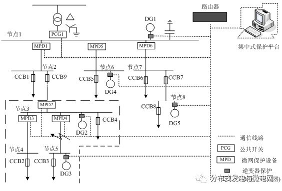
Centralized protection can facilitate the analysis of comprehensive information on the entire network, so as to accurately and quickly determine the location of the fault and the cause of the fault. The centralized protection scheme for microgrid equipment is shown in Figure 1.
It is mainly composed of a protection device and a protection control platform. The main functions of the microcomputer protection equipment include: collection and calculation of electric energy information, analysis of data according to protection algorithm model analysis, transmission of operation results to the upper control center, reception of control signals of the centralized protection center, and execution of instructions and monitoring of the upper control center. Device status [2].
The monitoring device and intelligent protection unit selected in the system all support IEC61850 communication, which can facilitate convenient networking and form a unified network with the centralized protection platform.
Figure 1 Microgrid equipment centralized protection scheme

The centralized protection center analyzes the fault of the data information of the microcomputer protection equipment to determine whether the equipment is in normal operation state. If a fault occurs, the corresponding protection measures should be taken according to the fault condition. Centralized protection can analyze and compare the information of on-site monitoring equipment to determine the fault location [3].
As shown in Figure 1, when the F node is not working properly, the protection devices MPD1 and MPD4 will detect a positive fault, and the system will judge the corresponding end protection and backup protection through analysis and comparison. At this time, MPD4 is used as the end protection. Should act first, MPD1 for backup protection.
1.2 Local protection scheme for equipment
When there is a problem in the microgrid protection communication system, since the local device cannot receive the action instruction of the upper centralized control platform, the site protection device should have the ability to protect according to the local settings, and detect and judge the fault according to the local information to complete the device. Protection action [4].
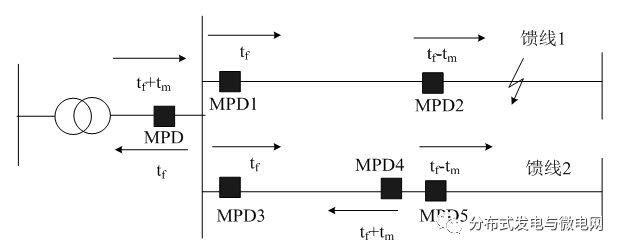
The protection supervision action connection can be determined according to the system failure judgment result and delay. As shown in Fig. 2, tf is the response time of the protection action, and tm is the action response delay time, which can usually be set to 20ms. In addition, the circuit can be short-circuit protected by means of an electronic circuit breaker.
Figure 2 Action sequence of protection actions

When a fault occurs at the line F, the protection devices MPD, MPD1, and MPD2 will detect the system fault at the same time, but the MPD2 will take priority action, while the backup protection MPD and MPD1 will delay the action as needed. Often, the scale of the microgrid is relatively small, there is no longer transmission line, and there is basically no case where the power source is connected through a feeder. Therefore, the protection scheme can meet the protection requirement [5].
The main protection settings for the protection device MPD are:
(1) Power direction protection.
The power flow direction of the microgrid is not fixed. When it is necessary to identify the fault direction, the power protection device is added.
(2) System ground fault protection.
When a single-phase ground fault occurs in a TN system, the zero-sequence current component of the system is often difficult to detect. At this time, it can be judged whether a single-phase ground fault occurs by calculating whether the sum of the four-phase currents of the system is zero.
(3) System overcurrent protection.
When the grid has an asymmetrical short circuit fault, the current of the system's negative sequence current will be very large, so the system can be protected by detecting the negative sequence current.
(4) Voltage fault protection
Voltage fault protection is often at the system common connection point or integrated into the system inverter. The purpose of the undervoltage protection of each common connection point of the system is to ensure that the system operates normally alone when the external power grid is not operating properly.
At the same time, when problems occur inside the system, the system can be effectively cut off to ensure the safety of the external power grid. In order to ensure the fault traversal capability of the distributed power supply, the protection action time limit of the common connection point should not be greater than the distributed power protection unit [7].
(5) Grid frequency protection.
The setting position of the system frequency protection is the same as the voltage protection. The protection action time limit decreases as the frequency deviation increases.
(6) Electronic circuit breaker protection.
The electronic circuit breaker protection function is comprehensive and has strong protection capability. It is usually equipped with overload long delay protection and overload instantaneous action protection. The protection time of the overload delay action is calculated according to the effective value of the system current [8].
1.3 Protection logic of automatic measurement and control unit
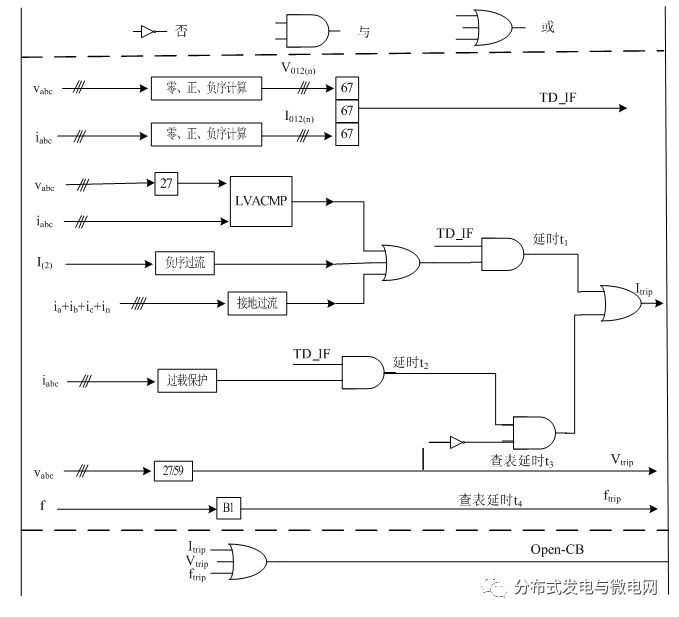
The automatic measurement and control unit is the core equipment of microgrid protection control. It can easily realize the protection function of the microgrid by virtue of its powerful measurement and control capability. The protection logic of the automatic measurement and control unit is shown in the figure below [9].
Figure 3 control protection logic diagram

Reliable and effective protection of the system through a combination of centralized protection and in-situ protection.
2 Microgrid protection configuration analysis
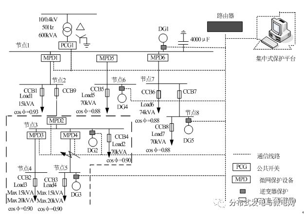
Assume that a microgrid structure is shown in Figure 4. The rated capacity of DG1 is 600kVA, the rated capacity of DG2 is 400kVA, the rated capacity of DG3, DG4 and DG5 is 50kVA, and the maximum output value of system current is 1.2 times of rated capacity, which is calculated to be 1.03kA and 0.69kA respectively.
Figure 4 Microgrid system centralized protection scheme

The rated current of the system electronic circuit breaker is selected to be 1.2 times the maximum load current of the system. The instantaneous overload action current selects 2 times or more of the current of the electronic circuit breaker. Although the rated current is only 25A at the 1# circuit breaker, the peak current in the system often exceeds several tens of amperes. In order to prevent the switch from malfunctioning due to disturbance, the instantaneous circuit is interrupted. The current is taken as 100A.
As shown in Table 1. The fault operation time is selected for 40ms, and the long-term overload current can be appropriately increased according to the maximum load of the line. The operation time of the 8# and 9# electronic circuit breakers is set to 5S, and the operation time of the remaining electronic circuit breakers is 4S. The protection action current value and time setting of the intelligent protection device are shown in Table 2.
These protection action times are all for the local protection action time when the microgrid network is disconnected. When the system communication is normal, the system performs targeted resection according to the analysis result of the uploading information of the protection device, and the action time of the main protection is shortened to 0.07S, and the backup protection action time is shortened to 0.1S [10].
Table 1 System electronic circuit breaker parameter configuration table

Table 2 Protection action time setting

(2) System fault protection action.
A study was conducted on the occurrence of a two-phase earth fault on the line between CCB9 and MPD2.
1) The transition resistance is set to 0.2 ohms, the system load is maximized, and the system protection action is as shown in the table below.
Table 3 Protection device action

2) The over-resistance is set to 2 ohms, the system load is maximized, and the system protection is as shown in the following table.
Table 4 Protection device operation

At the same time, we also experimented with the system load being at a minimum, and the protection equipment can operate reliably. MPD1 and MPD2 can protect the line well even when CCB9 cannot operate under some fault conditions.
In addition, the unstable operation mode of the microgrid current is diverse. We verified the power quality protection of the system by the system power supply voltage and frequency, and verified the overload condition of the system by adjusting the load condition. Obtained an ideal protection effect.
3 conclusions
With the construction of new energy and smart grids, distributed power structures are becoming more and more popular in distribution networks. Based on the characteristics of microgrid structure, this paper constructs a microgrid centralized protection control platform and introduces the configuration of microgrid protection equipment.
In order to cope with the loss of centralized control functions, the local protection of the microgrid was set. The microgrid protection system was tested by experiments and obtained ideal results.
Wire Condenser
The condensing unit is used for refrigerator temperature control devices, air conditioners, heat pumps and coolers. They are called [gas refrigerants" by compression in the form of heat, then pumped through the coil system, and heated and cooled by the coiled air. The condenser unit is mainly used in commercial refrigeration systems and industrial refrigeration systems. The condensing unit mainly consists of Mono-Blocks For Cold Storage,Semi Hermetic Condensing Unit,Box Type Condensing Unit ,we can follow the customer's requirements to produce the correct size of the condensing unit.
Wire Condenser,Cold Room Condenser,Evaporator Condenser,Refrigerator Condenser
FOSHAN SHUNDE JUNSHENG ELECTRICAL APPLIANCES CO.,LTD. , https://www.junshengcondenser.com