Flexible conveyor range:
Single power supply: +5V to +12V
Dual Supply: ±2.5V to ±5V Single
Bit-gain stability: 500MHz (G=1)
High output current: 190mA
Output voltage swing: ±4. 0v
High slew rate: 1800v/μs
Low supply current: 5. 5ma
Low supply current: 100uA.
Bandwidth +5v Op Amp: 200MHz (G=2)
OPA690 block diagram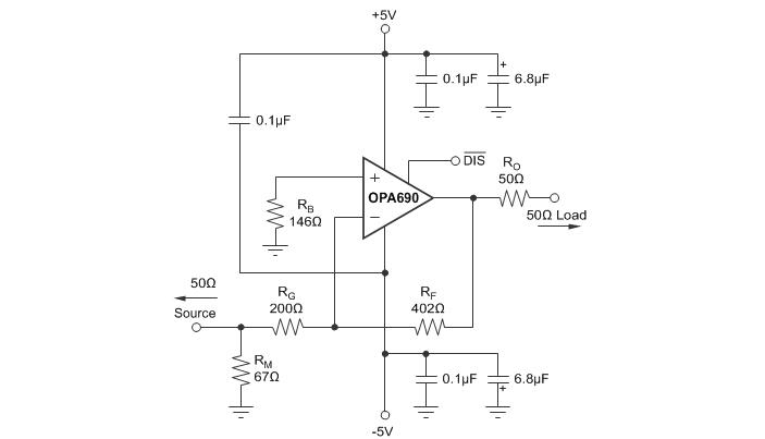
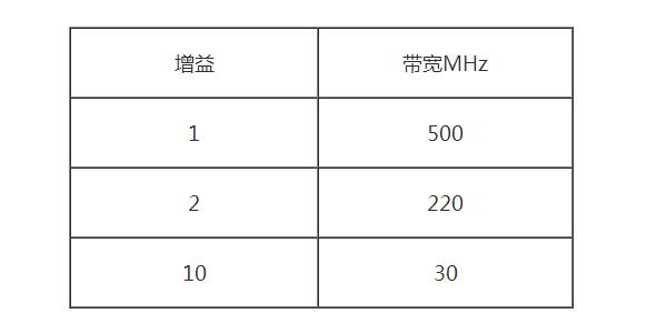
Table 1 Relationship Between Gain and Bandwidth (with ±5V Power Supply)
±2.5~±5V Dual Supply or +5~+12V Single Supply
Output voltage range ±4V
Output current 190mA
Disable current 100uA
How to use the opamp OPA690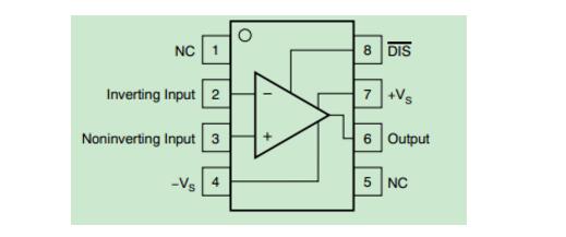
Figure 1 pin layout
It is the same as the general opamp pin layout. The only difference is that the 8-pin port is a low power mode control port. When this pin is left floating or high, it is in normal operation. If it is set low, the supply current will drop to 100uA. The chip stops working and is in power saving mode.
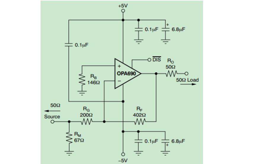
Figure 2 reverse amplifier circuit
In actual application, the circuit is connected according to the above figure. The figure above shows the magnification of 2 times and the requirement of 10 times amplification. You need to select RF as 1KΩ (200Ω~1.5KΩ can be satisfied) and RG=100Ω. If impedance matching is needed, it will be The RM is connected in parallel to RG to adjust the input impedance. At the same time, after the three resistors are determined, the value of RB is determined again so that the DC resistances of the non-inverting input and the inverting input are equal to each other to determine the value of RB. This causes the input DC bias current to be reduced to a minimum. The 0.1uF capacitor acts as a voltage coupling to reduce waveform distortion caused by the second harmonic output.
OPA690 Usage Results and ProblemsWhen the input signal frequency is 100KHz, the signal can be amplified by 10 times, and the frequency is gradually increased. When the signal is adjusted to 20MHz over 5M, the amplified output signal gradually becomes smaller, and the output signal becomes distorted when it approaches 20MHz. . Try to increase the frequency when the distortion is even more severe.
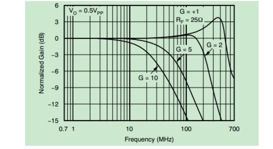
Figure 3 Small Signal Input Frequency Response Curve
Compared with the above figure, we can see that, in the case of small signal input, when the gain is 10, the input signal frequency is greater than 4MHz, the output begins to decline, more than 10MHz decline more powerful, which concluded that in the amplification When the multiple ≥10, the OPA690's high frequency performance is not good.
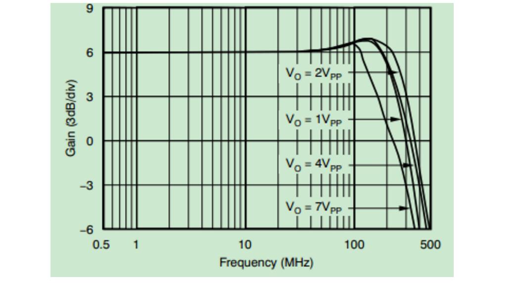
Figure 4 Large Signal Input Frequency Response Curve
When the input signal is a large signal, the frequency of the input signal can be significantly improved when the amplification factor is 10, and the high frequency performance is slightly better when the large signal is input.
OPA690 notesFor amplification applications, Rf is best recommended in the data sheet, especially when doubling and five times magnification.
When the OPA690 is used as an emitter follower, the feedback loop cannot be directly short-circuited, and the 25Ω resistor must be connected.
OPA690 is best not to use the most emissive device, easy to produce self-excitation
When G "1", Rf value range is limited, 200Ω "Rf" 1.5KΩ
The empirical value of Rf||Rg is Rf||Rg “300Ω
Extra supplement:
OPA690 for filter circuit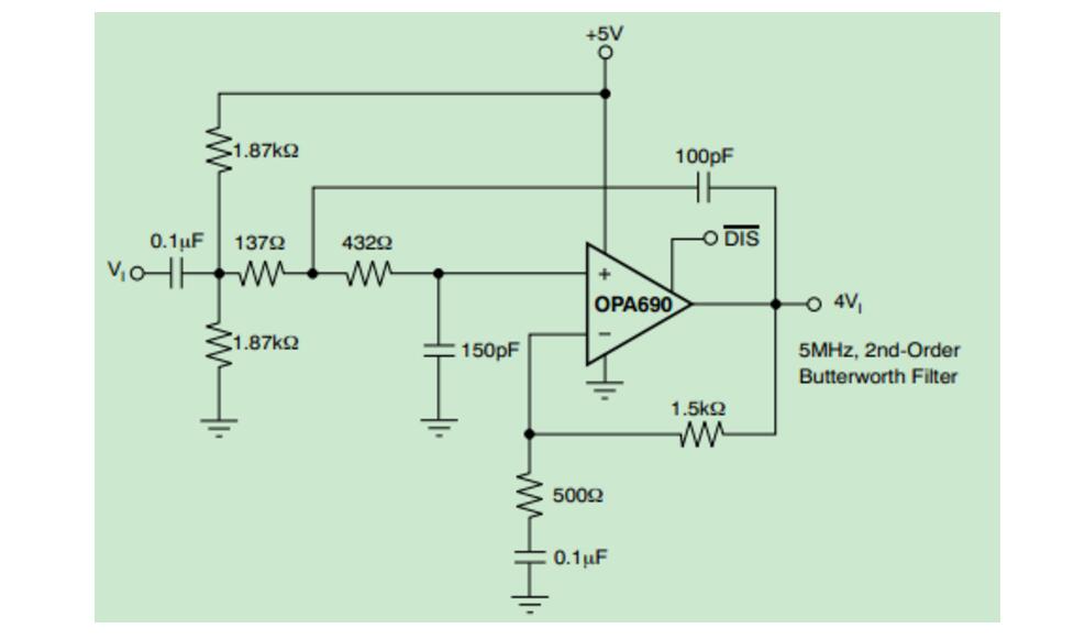
Fig. 5 High-frequency Butterworth filter
The above figure shows a second-order band-pass filter with a center frequency of 5 MHz. It can also amplify the signal by a factor of three.
In addition, the active filter is generally only able to do about 500K, so do not worry about the analog bandwidth of the op amp, as long as the op amp with a good slew rate is selected. As for the impact of analog bandwidth on the signal, only OPA690, which can disable the bandwidth, can limit the bandwidth of the signal. The others are less strict. A 5M filter, through a 4M square wave, will not produce large waveform distortion, which is not related to the cutoff frequency of the filter, and is related to the group delay of the filter. So usually we say that the filter cut-off frequency refers to the single-frequency signal, which is the sine wave, or the main frequency of the wide-spectrum signal. Don't worry about the effect on harmonics.
Aluminum Electrolytic Capacitors
Aluminum Electrolytic Capacitors
Large Electrolytic Capacitor,HV Electrolytic Capacitors,Aluminum Electrolytic Capacitors
YANGZHOU POSITIONING TECH CO., LTD. , https://www.pst-thyristor.com