In the control system, use the analog quantity of the PLC to control multiple inverters. Since the characteristics of the inverter itself that produce strong interference signals and the analog anti-jamming capability are not as strong as the digital anti-jamming capability; therefore, in order to maximize the elimination of the inverter For analog interference, more stringent measures need to be taken in terms of wiring and grounding.
one. About wiring
1. Signal and power lines must be routed separately
When using an analog signal to remotely control the inverter, in order to reduce the amount of analog signal from interference from the inverter and other equipment, separate the signal wire that controls the inverter from the strong electric circuit (main circuit and sequence control circuit). The distance should be more than 30cm. Even in the control cabinet, the same wiring specification must be maintained. The maximum length of the control loop between this signal and the inverter must not exceed 50m.
2. Signal lines and power lines must be placed inside different metal pipes or metal hoses, respectively
Since the two three-prong inverters of the water system are 30m and 20m away from the control cabinet, the signal lines connecting the PLC and the inverter are not easily placed in the metal pipe and are easily subject to interference from the inverter and external equipment. Since the inverter has no built-in reactor, the input and output power lines of the inverter will have strong interference to the outside. Therefore, the metal pipe or metal hose for placing the signal line should always extend to the control terminal of the inverter. Ensure that the signal line is completely separated from the power line.
3. Two-strand twisted shielded wire should be used for the analog control signal line, and the wire size is 0.5-2mm2.
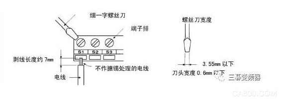
Be sure to pay attention to the wiring, cable stripping should be as short as possible (5-7mm or so), at the same time after the stripping of the shielding layer should be wrapped with insulation tape to prevent the shielding line from contact with other equipment to introduce interference.
4. In order to improve the ease and reliability of wiring, it is recommended to use crimper terminals on the signal line.
Crimp terminal selection as shown below:

5. If no crimp terminal is used, please pay attention when wiring:

two. About grounding
1. The grounding of the inverter should be grounded separately from the PLC control loop. In the event that the grounding cannot be guaranteed alone, the control loop grounding may float in order to reduce the interference of the inverter to the controller, but the inverter must ensure a reliable grounding. In the control system, it is recommended that both sides of the shielded signal line of the analog signal line be floated, and at the same time, because the PLC and the inverter share a single earth on the unit, it is recommended that the PLC be grounded separately or the PLC and the unit be grounded when possible. Insulation.
2. Grounding of the frequency converter
400V class: C type ground (ground resistance less than 10Ω).
Do not share the grounding wire with the welder and power equipment.
The grounding wire should be in accordance with the wire diameter specifications specified in the technical standards for electrical equipment.
For example, the recommended grounding wire diameter of 35KW is 22 mm2, and the recommended grounding wire diameter of 87KW is 50 mm2.
The ground wire is as short as possible. Due to the leakage current generated by the inverter, the potential of the ground terminal is not stable because it is too far away from the ground point.
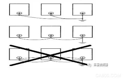
When using more than two inverters, do not loop the ground wire. Pictured:

3. Distance between the inverter and the motor.
In the case where the wiring distance between the inverter and the motor is long, high-harmonic leakage current from the cable may adversely affect the inverter and peripheral equipment. Therefore, in order to reduce the interference of the inverter, the carrier frequency of the inverter needs to be adjusted. Please refer to the following table:


Sales Hotline: 13989502020
Service Hotline
SANCH inverter website: http://
More information you can choose to visit the official website to understand or download, if necessary, you can contact us directly, or join the QQ technology exchange group and other ways to consult, Sanhe team will be happy to help you.
QQ technical exchange group: 237648030

Incremental encoders provide speed, direction and relative position feedback by generating a stream of binary pulses proportional to the rotation of a motor or driven shaft. Lander offers both optical and magnetic incremental encoders in 4 mounting options: shafted with coupling, hollow-shaft, hub-shaft or bearingless. Single channel incremental encoders can measure speed which dual channel or quadrature encoders (AB) can interpret direction based on the phase relationship between the 2 channels. Indexed quadrature encoders (ABZ) are also available for homing location are startup.
Incremental Encoder,6Mm Solid Shaft Encoder,Hollow Rotary Encoder,Elevator Door Encoder
Jilin Lander Intelligent Technology Co., Ltd , https://www.jllandertech.com