The temperature detection and control of the motor plays a vital role in industrial production. At present, there is a lack of real-time online monitoring system for the rotor temperature of the motor. The motor overtime and overload operation will cause the motor temperature to rise sharply, which will affect the safety and stability of industrial production, and directly cause huge economic losses. Due to the complicated structure inside the motor, the rotor is running at high speed during operation, and wired measurement cannot be realized. Therefore, the temperature monitoring system of most motors is mainly based on non-direct contact measurement, but these methods have large measurement error, long delay time, etc. Disadvantages. In this paper, a real-time online monitoring system for motor temperature based on TMP275 is studied. MSP430 is used as the core processor. Real-time online monitoring of motor equipment temperature is realized by infrared wireless transmitting module. The experimental results show that the system has high measurement accuracy and error. Small, fast response, reliable operation, can be widely used in high-precision instrumentation control systems.
1 module circuit hardware design
1.1 Overall structural design
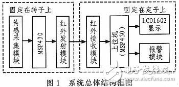
The design uses the MSP430 as the controller. The MSP430 is an ultra-low-power microcontroller that operates from +3.3 V. Ideal for long-term applications where battery power is applied. The internal temperature of the motor is measured by the TMP275, sent to the MSP430 for processing, and the processing result is sent to the infrared transmitting module fixed on the rotor. The infrared receiving module fixed on the stator sends the received data to the upper computer to realize real-time online monitoring. The overall structural block diagram of the system is shown in FIG. 1 .
1.2 Sensor acquisition circuit design
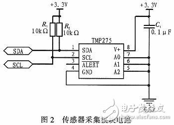
The TMP275 digital temperature sensor chip used in this design is powered by +3.3 V and integrates an I2C bus interface and a 16-bit AD conversion circuit. In the operating temperature range of -55 to +127 °C, the TMP275 digital sensor only produces an error of +0.5 °C. At the same time, compared with the analog temperature sensor, the digital signal output by the TMP275 can be directly sent to the controller for processing, avoiding the analog-digital The cumbersome and unrealistic shortcomings of the conversion circuit. The design of the acquisition circuit is shown in Figure 2, where A2, A1, and A0 are their address pins, and they are grounded at the same time. The chip converts the acquired temperature into a 16-bit binary number: the first bit is the sign bit, followed by the integer part 7 bits, the fractional part 4 bits, and the last 4 bits are all 0s. The specific temperature format is as follows:
+temperature: 0XXX XXXX XXXX 0000;
- Temperature: 11XX XXXX XXXX 0000.
The highest digit represents the sign bit: 0 for "+" and 1 for "-".
1.3 Installation of the test device
Infrared transceivers require reliable packaging due to the working environment. The following problems should be considered in packaging: to prevent the influence of electromagnetic interference on the circuit, and to have sufficient mechanical strength, to facilitate installation and fixation, and to have a certain temperature resistance.
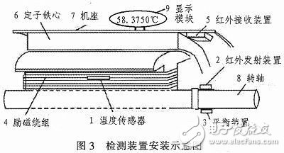
The installation of the device is shown in Figure 3; the temperature sensor is embedded in the excitation winding or other point that is easy to overheat; the infrared emission module is fixed on the rotating shaft of the motor by screws and separated by an insulating layer; the infrared receiving device is installed at the base of the machine. The inner wall of the part is aligned with the infrared emitting device as much as possible to ensure good reception.
2 software design
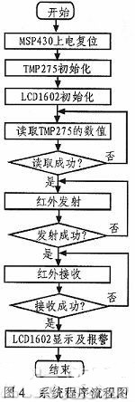
The software part mainly includes: firstly powering on the controller MSP430, TMP275 sensor chip, LCD1602 initialization, and then the MSP430 sends an instruction to request to read the TMP275 temperature value. If the MSP430 does not receive the temperature value sent from the TMP275, the MSP430 transmits again. Request to read the temperature command, wait until the reading is successful, and send the value to the infrared sending module, wait for the infrared transmitting module to successfully transmit the value, and the infrared receiving module waits for the data to be received. After confirming that the value is successfully received, the data is finally sent to the LCD1602. Module and alarm module. The above is the overall software flow plan of the design temperature monitoring system. The overall flow chart of the system is shown in Figure 4.
3 Experimental results
This design mainly tests the accuracy of the temperature sensor and the response time.
3.1 TMP275 and DS18B20 temperature measurement comparison
The TMP275 temperature sensor chip operates at -55 to +127 °C. A single-digital DS18B20 temperature sensor with the same resolution is selected as the comparison object. The sensor is buried in a closed oven with controlled temperature. After a certain period of temperature change, a series of measured temperature and actual temperature values ​​are obtained. The experimental results are shown in Table 1. Here, the temperature measured by the PT100 platinum resistance thermometer is recorded as the actual temperature.
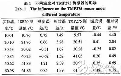
As can be seen from the above table, the maximum temperature difference measured by DS18B20 is 1.21 °C at different temperatures, and the maximum relative error is 7.49%. Compared with DS18B20, the maximum temperature difference measured by TMP275 is 0.48 °C, and the maximum relative error is 4.4 0%. .
In summary, the TMP275 temperature sensor has a high measurement accuracy and a small relative error within the operating temperature range, which fully meets the requirements for the motor temperature detection system.
3.2 Comparison of TMP275 response time
From the moment the controller sends a temperature acquisition command to the temperature chip to the moment the controller receives the temperature data, the time required for this temperature acquisition process is called the response time of the sensor. Since the time involved here is generally short, it is necessary to use the timer of the MSP430 to measure. From the moment after the temperature acquisition command is sent by the host computer MSP430, the timing stops when the MSP430 receives the temperature data, and it is recorded as a response time. The response time of PT100 platinum resistance thermometer, DS18B20 and TMP275 was measured by experiments. As shown in table 2.
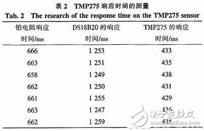
As can be seen from the experimental data in the above table, the DS18B20 response is the slowest, which takes about 1 250 ms. The platinum resistance thermometer response takes about 660 ms. Compared to the above two sensors, the TMP275 response time is only 430 ms. In summary, the TMP2 75 temperature sensor is more responsive than the single-bus DS18B20 and faster than the platinum resistance thermometer. Therefore, it is basically believed that the monitoring of the rotor temperature of the motor by the TMP275 is real-time.
4 Conclusion
In view of the many defects of the domestic motor rotor temperature monitoring system, this paper selects the TMP275 temperature sensor chip to design a detection system that accurately and quickly reads the internal temperature of the motor through infrared transmission technology. The developed temperature monitoring system works reliably, can achieve the required control precision, high temperature measurement accuracy, short reaction time, accurate remote data transmission, online control, high application value, can be applied to power plants, Automotive engines and other fields.
Tips:
· This IPhone 6S Plus LCD Digitizer Replacement includes the components as mentioned above, it does not include the small parts. Please do not confuse it with the iPhone LCD Assembly with Small Parts.
· Please test LCD assembly function one by one 100% before installation.
iPhone 6S/6S Plus LCD Digitizer
IPhone 6S Plus LCD,IPhone 6S Plus LCD Screen,IPhone 6S Plus Replacement
Shenzhen Aokal Technology Co., Ltd. , https://www.aokal.com