The electrically erasable memory is a readable and writable storage device, which is abbreviated as E2PROM in English, and is mainly used for data storage. Among them, 24CXX series memory is a kind of E2PROM which is more commonly used. It is widely used in various household appliances, such as IIC bus control color TV, storing various data such as brightness and surface balance of the normal working of the whole machine. However, such a memory is highly susceptible to static electricity and damages the lost stored data, which makes it difficult for the IIC bus to control color TV maintenance. In order to make the 24CXX series memory purchased in the market contain the data of the whole machine working normally written by the original manufacturer, the following describes a serial memory copyer, which can write the data in the memory E2PROM of the home appliance. Go to the blank memory.
Analyze the schematic circuit diagram of the copyer. The main control chip adopts the single-chip AT89C2051. The chip itself does not have the hardware IIC system. Therefore, the pure II analog bus is used in the production, and the SDA is connected to the IC4 (19) pin. SCL is connected to IC4 (18) pin.
The IC4 (14) pin is used for the indicator LED drive, and the (15) pin is used to activate the input of the key SB. C3 and R4 form a power-on reset circuit. B and C4, C5 form a clock oscillation circuit. Add power to form a simple microcontroller application system. IC2 and IC3 are two 8-pin DIP sockets for inserting two 24CXX memories, of which IC2 is the source memory and comes from the EEPROM in the color TV. IC3 is the target storage, that is, the commercially available blank E2PROM. The address pins AO, A1, and A2 of the source memory are connected to the common ground, and the target memory is connected to the public ground except A2 and VCC. IC2, IC3 4 feet grounded, 5 feet for the data line SDA, 6 feet for the clock line SCL, 7 feet for the test end, under normal ground, 8 feet for the power supply Vcc (5V).
From the socket & TImes; access 9 ~ 12V DC power supply, after the three-terminal regulator fCl (78L05) voltage regulator, to provide 5V voltage to the entire circuit, diode VD2 to prevent external power supply polarity reverse connection caused by circuit damage. C1 and C2 are used for filtering.
When using, insert the source storage and target memory on IC2 and IC3 respectively, turn on the power, the LED will flash at low speed, indicating that it has been working normally, then press the start button SB, then the LED is always on, indicating that it is being copied. Wait for a period of time about 20s. The LED flashes again, indicating that the data has been copied to the target memory, that is, the copy is completed, and the power is removed. At this time, the content data in the two memories is completely identical, and the target insertion memory is unplugged, which can be used as a maintenance spare, and the source memory can be plugged back into the color TV to work normally.
The main control chip 89C2051 is a commercially available single-chip microcomputer. The software program must burn the binary machine code through the programmer. The machine code can only be used for programming. If you want to read it, you need to have the MCU compiler software to translate.
This copyer is only applicable to the 24C08/C02/01 series memory, and the 24C16 or higher memory cannot be applied because the read/write format is different from the above series memory. 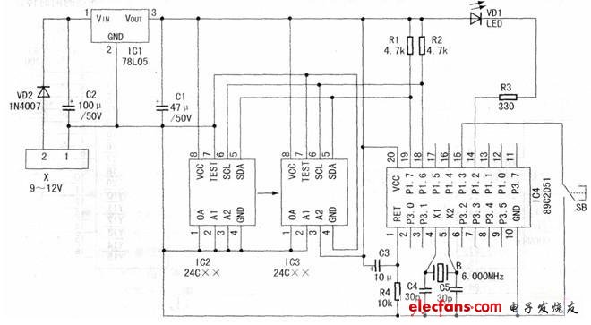
Portable Megaphone,High Quality Megaphone,Wifi Megaphone,Megaphone Small
yucheng county huibang electric technology ltd , https://www.hbspeaker.com