In the MCU system, if the IO resources of the parallel port are not enough, then we can use the 74LS164 to expand the parallel IO port, saving the IO resources of the MCU. The 74LS164 is a serial input parallel output shift register with a clear terminal.
Timing analysis, single-chip serial port timing microcontroller serial port for the display port should work in the mode transmission state, the timing is as shown. As can be seen from the timing diagram, when a data is input to the serial port transmission buffer SBUF, the serial port passes the 8-bit data from the low to the high (ie, from D0 to D7) at the baud rate of Fosc/12. The RXD pin outputs. When the bit is transmitted, the interrupt flag TI is set to "1" to end a transmission process. What should be noted here is the order of the serial port number, which is the key to the correct cooperation between the serial port of the MCU and the 74LS164.
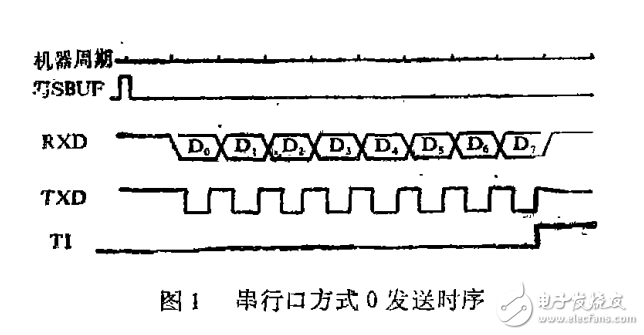
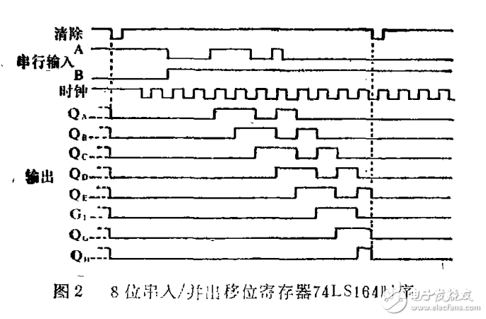
Figure 2 shows the operation timing of the 8-bit serial input, parallel output shift register 74LS164. As can be seen from Figure 2, when enable B (pin 2) is low, the register disables input data. When B is high, data can be input from terminal A (pin 1). As shown in Fig. 2, the data input first is first output from (pin 3). When the register 74LS164 receives the 8-bit data, the first input 1 is shifted to the Q (pin 13) output, and the Qa terminal is the last received 1 bit.
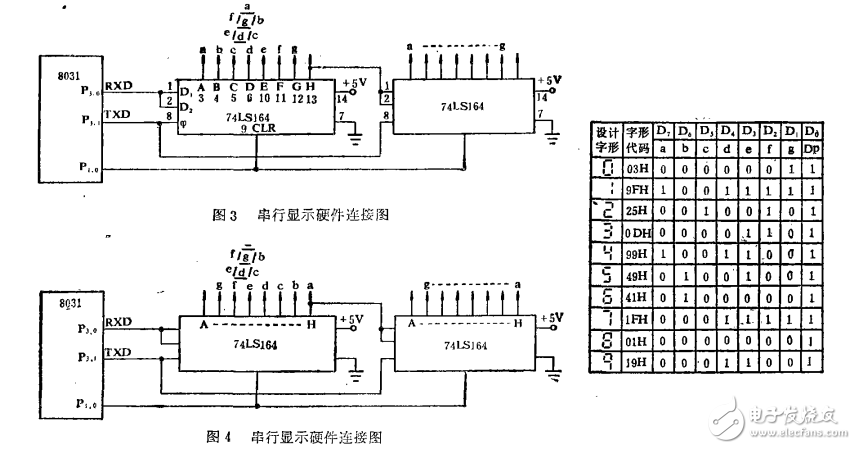
From the above timing analysis of the serial port of the MCU and the 74LS164, the shift register first receives the lowest bit D0 of the serial port output of the MCU. Finally received the highest bit D7 of the byte. Therefore, after receiving the 8-bit data, the output of the shift register QH terminal is D0. And the QA output is D7. The reason for the error in the two articles mentioned above is that this important feature is ignored. The hardware circuit they give is shown in Figure 3. The glyph code and truth table are shown in the table.
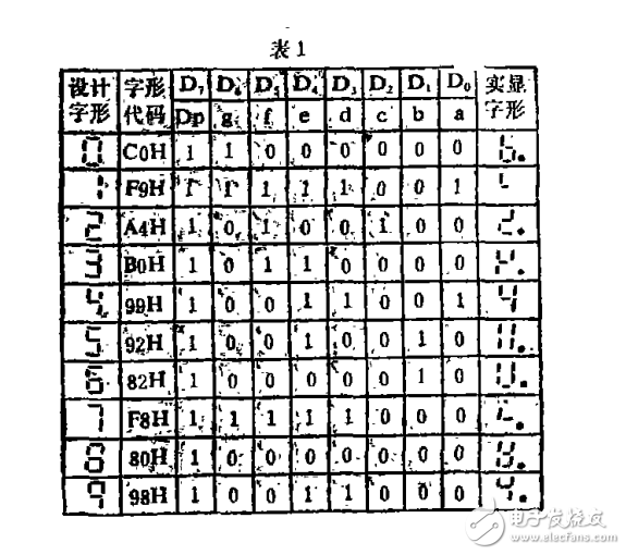
As can be seen from Table 1, the glyph code treats the segment code a as the D0 bit and the segment code h as the D7 bit in turn. When the shift register receives a complete glyph code, QA outputs not the segment code a, but the segment code h (h is a decimal point or not.) The result of this processing is that the segment code order of the output is just the opposite. Therefore, the displayed glyphs are wrong. The wrong glyphs (h with a decimal point) are listed on the right side of Table 1. To display the correct glyph, the glyph code should be adjusted when using the circuit shown in Figure 3. The adjusted glyph code and truth table are shown in Table 2. When such a glyph code is input into the 74LS164, the segment codes a to h are sequentially outputted on the output pins QA to QH, thereby correctly displaying the content to be displayed.
In some cases, the designer still wants to use the glyph codes listed in Table 1, then just adjust the connection between the display and the 74LS164. The hardware circuit is shown in Figure 4.
Through the analysis of the serial port of the MCU and the timing of the 74LS164, two correct software and hardware combination methods are given. In the successful intelligent centrifugal switch disconnecting speedometer, the author uses the font code listed in Table 2 to match the hardware shown in Fig. 3, and the results are satisfactory. In addition, some designs may also encounter the problem of 8 bits combined with the serial output shift register 74LS165 and the serial port of the MCU. The research method should still start from the timing, which is similar to the method described in this article.
The proteus simulation diagram and code are attached.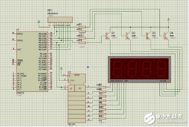
#include"reg51.h"
#define HIGH 1
#define LOW 0
#define SEG_PORT P0
Sbit DATA = P0^4;
Sbit CLK = P0^5;
Unsigned char TImer0IRQEvent = 0;
Unsigned char TIme1SecEvent = 0;
Unsigned int TImeCount = 0;
Unsigned char SegCurPosition = 0;
Code unsigned char SegCode[10] = {~0x3F,~0x06,~0x5B,~0x4F,~0x66,~0x6D,~0x7D,~0x07,~0x7F,~0x6F};
Code unsigned char SegPosition[4] = {0xFE,0xFD,0xFB,0xF7};
Unsigned char SegBuf[4] = {0};
Void LS164_DATA(unsigned char x)
{
If(x)
{
DATA = 1;
}
Else
{
DATA = 0;
}
}
Void LS164_CLK(unsigned char x)
{
If(x)
{
CLK = 1;
}
Else
{
CLK = 0;
}
}
/************************************************* *********
*Function name: LS164Send
*Input: byte single byte
* Output: None
* Function: 74LS164 sends a single byte
************************************************** *********/
Void LS164Send(unsigned char byte)
{
Unsigned char j;
For(j=0;j"=7;j++)
{
If(byte&(1"((7-j)))
{
LS164_DATA(HIGH);
}
Else
{
LS164_DATA(LOW);
}
LS164_CLK(LOW);
LS164_CLK(HIGH);
}
}
/************************************************* *********
*Function name: SegRefreshDisplayBuf
*Input: None
* Output: None
* Function: Digital tube refresh display cache
************************************************** *********/
Void SegRefreshDisplayBuf(void)
{
SegBuf[0] = TimeCount%10;
SegBuf[1] = TimeCount/10%10;
SegBuf[2] = TimeCount/100%10;
SegBuf[3] = TimeCount/1000%10;
}
/************************************************* *********
*Function name: SegDisplay
*Input: None
* Output: None
* Function: Digital tube display data
************************************************** *********/
Void SegDisplay(void)
{
Unsigned char t;
SEG_PORT = 0x0F;
t = SegCode[SegBuf[SegCurPosition]];
LS164Send(t);
SEG_PORT = SegPosition[SegCurPosition];
If(++SegCurPosition 》= 4)
{
SegCurPosition = 0;
}
}
/************************************************* *********
*Function name: TimerInit
*Input: None
* Output: None
* Function: timer initialization
************************************************** *********/
Void TimerInit(void)
{
TH0 = (65536 - 5000)/256;
TL0 = (65536 - 5000)%256;
TMOD = 0x01;
}
/************************************************* *********
*Function name: Timer0Start
*Input: None
* Output: None
* Function: timer start
************************************************** *********/
Void Timer0Start(void)
{
TR0 = 1;
ET0 = 1;
}
/************************************************* *********
*Function name: PortInit
*Input: None
* Output: None
* Function: I/O initialization
************************************************** *********/
Void PortInit(void)
{
P0 = P1 = P2 = P3 = 0xFF;
}
/************************************************* *********
*function name: main
*Input: None
* Output: None
* Function: Function theme
************************************************** *********/
Void main(void)
{
PortInit();
TimerInit();
Timer0Start();
SegRefreshDisplayBuf();
EA = 1;
While(1)
{
If(Timer0IRQEvent)
{
Timer0IRQEvent = 0;
If(Time1SecEvent)
{
Time1SecEvent = 0;
If(++TimeCount 》= 9999)
{
TimeCount = 0;
}
SegRefreshDisplayBuf();
}
SegDisplay();
}
}
}
/************************************************* *********
*Function name: Timer0IRQ
*Input: None
* Output: None
* Function: timer interrupt function
************************************************** *********/
Void Timer0IRQ(void) interrupt 1
{
Static unsigned int cnt = 0;
TH0 = (65536 - 5000)/256;
TL0 = (65536 - 5000)%256;
Timer0IRQEvent = 1;
If(++cnt 》= 200)
{
Cnt = 0;
Time1SecEvent = 1;
}
}
A new experience of true wireless
Automatic seconds connection, can be used with headphones
Professional sound engineering technology
Case Cube/acoustic clear sound reproduction
customized stainless steel acoustic structure, high quality grahene hoop system and obvious environmental noise attenuation will open up a pleasant journmey journey for you to enjoy the sound.
Built-in microphone/ Effective noise reduction/ Clear call/ Easy to carry
Sports can't be abandoned more freely
Close ergonomic design, close to the ear, even wearing for a long time can also enjoy comfortable experience.
And can form a triangular stable support with the ear, even if running and riding, vigorous fitness is still close to the ears, wildly shake off.
Bluetooth Earbuds,True Wireless Earbuds,Wireless In Ear Gaming Headset,Wireless Bluetooth Headphones
Guangzhou HangDeng Tech Co. Ltd , http://www.hangdengtech.com