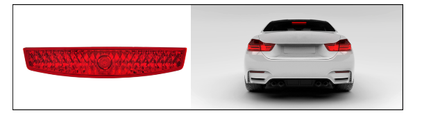
CHMSL stands for the central high brake light and is installed above the left and right brake lights (also called brake lights) of the vehicle. According to the regulations of the National Highway Traffic Safety Administration of the United States, when the braking system is working, CHMSL will provide clear and precise information to the rear drivers, telling them that they must slow down. Because CHMSL is installed outside the left and right brake lights, it is also called the "third brake light." In addition to the brake light function, some vehicles (such as pick-up trucks) also have a reversing light integrated in the CHMSL.
CHMSL installation using discrete components
In modern vehicles, the lights inside the CHSMSL are mainly based on light emitting diode (LED) light strings. A transistor circuit is used to drive the LED string in CHMSL. In contrast to switching circuits, the CHMSL LED driver circuit is usually a linear circuit; that is, the LED is driven by a circuit whose transistor operates in its linear region.
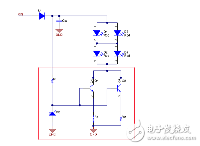
Designers often use discrete resistors and low-side bipolar junction transistors (BJTs) to implement discrete component-based LED driver circuits in the CHMSL module. Figure 1 shows an example of a discrete LED driver circuit for CHMSL. In this circuit, CHMSL consists of two LED strings, where each string is built on two series-connected red LEDs. The BJT is located on the underside of the LED.
Thermal considerations
Heat dissipation must be considered when designing linear LED driver circuits. Circuit design and component selection must ensure that the component does not reach the temperature point that caused the damage. From the schematic of Figure 1, you can see that as the supply voltage increases, the voltage across the BJT and the resistor also increases, increasing the power consumption of these components. More power consumption means higher temperatures. Therefore, in linear LED driver applications, controlling the input voltage range helps solve most of the thermal issues.
To analyze the heat dissipation of the schematic in Figure 1, consider an example where the total current of the CHMSL LED is 90mA, so each LED string is driven at 45mA. Using the 16V supply voltage, the maximum voltage drop on the BJT, calculated by Equation 1, is 9V:
Equation 2 calculates the maximum power consumption of BJT as 0.81W:
Assuming a maximum operating ambient temperature of 85°C and using BJT in a small outline transistor (SOT)-223 package with a thermal resistance of 80°C/W, the maximum BJT junction temperature calculated by Equation 3 is:
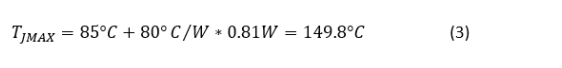
This calculation shows that the junction temperature is very close to the standard maximum allowable junction temperature of 150°C.
In order to increase the thermal performance of the circuit, two shunt transistors are used to dissipate the power dissipation. Even in the worst case, the maximum temperature can be kept below 150°C, as shown in Equation 4:
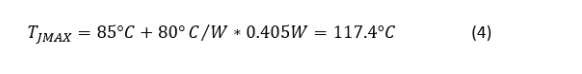
When using different BJT package types with higher thermal resistance, more BJTs are needed to distribute power consumption. The number and size of shunt transistors are based primarily on the LED current and the maximum power dissipation allowed by the transistor.
CHMSL installation application with integrated LED driver IC
Another way to drive the LEDs is to use a specific linear LED driver integrated circuit (IC), such as Texas Instruments' TPS92610-Q1, as shown in Figure 2. In this IC driver, both transistor and transistor driver circuits are integrated within the IC. The transistor still operates in its linear region. Since all components are integrated inside the IC, you only need the IC and a sense resistor to implement this solution.
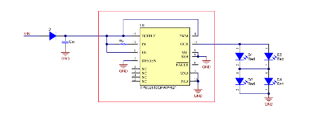
Figure 2: TPS92610-Q1 Integrated LED Driver
Consider heat dissipation again
Let us look at the heat dissipation problem in this design. Specifically, the IC's junction temperature. At the 16V supply voltage, Equation 5 calculates the maximum voltage drop on the IC to 11V:
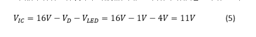
Assuming that the IC has the same 90mA current, the maximum voltage drop on the IC is 11V, and the thermal resistance is 52°C/W, Equation 6 calculates the maximum junction temperature:
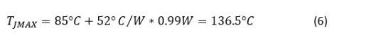
136.5°C The maximum specified IC junction temperature well below 150°C. Therefore, you only need one driver IC to operate the CHMSL LED string in the example.
The advantages of integrated solutions
A clear advantage of an integrated solution is the reduced number of components compared to discrete solutions. Reducing the number of components on the circuit board will significantly reduce space requirements.
Another key advantage is the accuracy of current regulation over the entire temperature range. As the LED's forward voltage changes with temperature, the driver IC can keep the current in the IC constant. This is in contrast to the discrete circuit shown in Figure 1, which does not regulate the current in the LED as the temperature changes.
The third advantage of the linear LED driver IC solution is that it has a diagnostic function that can detect LED circuit failures, such as LED open and short circuits, and notify the driver of the fault.
Finally, the application shown in FIG. 2 may be less expensive than in FIG. 1 when considering the number of components and the cost of each component.
More information
The CHMSL Automotive Linear LED Driver Reference Design is an integrated solution for driving CHMSL LED strings, including brake and reversing lights. Each lamp can be controlled independently by supplying power to its power supply line. The design uses three TPS92610-Q1 linear LED drivers that meet the automotive industry standard for low material cost and feature-rich solutions.
Ball Lenses are commonly used to improve signal quality in fiber coupling applications, or for use in endoscopy or bar code scanning applications. Ball Lenses feature short back focal lengths to minimize the distance needed from the Ball Lens to the optical fiber. Zoolied offers a variety of Ball Lenses in a range of substrates for performance in the ultraviolet to the NIR. Half-Ball Lenses are also available to ease mounting or system integration.
Zoolied N-BK7 Ball Lenses are glass spheres commonly used in fiber optic applications. Ball lenses are ideal for focusing light into optical fibers, or for fiber coupling.
Bk7 Ball Lens,K9 Ball Lens,K9 Optical Ball,5Mm Bk7 Ball
Zoolied Inc. , https://www.zoolied.com