There are three parts to this series, and Part 1 focuses on how to accurately estimate the jitter of a clock source and how it can be combined with the aperture jitter of the ADC. In Part 2, this combined jitter is used to calculate the SRN of the ADC and then compare it to the actual measurement. "Part 3" will show you how to further increase the SNR of the ADC by improving the aperture jitter of the ADC, and will focus on the optimization of the clock signal conversion rate.
Review of the sampling process
According to the Nyquist-Shannon sampling theorem, if the original input signal is sampled at a rate at least twice its maximum frequency, it can be fully reconstructed. Assuming a sample signal of up to 10MHz is sampled at a rate of 100 MSPS, it doesn't matter whether the signal is in the baseband from 1 to 10 MHz (the first Nyquist region) or undersampled in the higher Nyquist region from 100 to 110 MHz (please See Figure 1). Sampling in higher (second, third, etc.) Nyquist regions is generally referred to as undersampling or subsampling. However, anti-aliasing filtering is required in front of the ADC to sample the ideal Nyquist region while avoiding interference during the reconstruction of the original signal.
Figure 1 Two input signals sampled by 100MSPS show the same sample points brought by aliasing

Time domain jitter
Looking closely at a sample point, you can see how timing changes (clock jitter or clock phase noise) form amplitude changes. Due to the increase in input frequency due to undersampling of high Nyquist regions (eg, f1 = 10 MHz to f2 = 110 MHz), a fixed amount of clock jitter produces a greater amount of amplitude deviation (noise) from the ideal sample point. In addition, Figure 2 shows that the clock signal's own slew rate affects the change in sampling time. The slew rate determines how fast the clock signal passes through the zero crossing. In other words, the slew rate directly affects the trigger threshold of the clock circuit in the ADC.
Figure 2 Clock jitter forms more fast input signal amplitude error

If there is a fixed amount of thermal noise on the ADC's internal clock buffer, the slew rate is also converted to a timing error, which reduces the ADC's inherent window jitter. As shown in Figure 3, window jitter is not related to clock jitter (phase noise), but the two jitter components are combined at the sampling time. Figure 3 also shows that window jitter increases as the slew rate decreases. The slew rate is generally directly dependent on the clock amplitude.

Clock jitter causes SNR to decrease
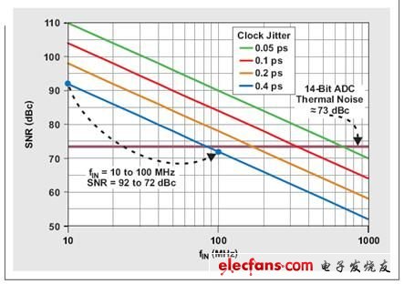
There are several factors that limit the SNR of the ADC, such as quantization noise (which is generally not noticeable in pipeline converters), thermal noise (which limits SNR at low input frequencies), and clock jitter (SNRJitter) (see Equation 1 below). ). The SNRJitter portion is limited by the input frequency fIN (depending on the Nyquist region) and is limited by the total clock jitter amount tJitter, which is calculated as follows:

SNRJitter[dBc]=-20&TImes;log(2Ï€&TImes;fIN&TImes;tJitter) (2)
As we expected, with a fixed amount of clock jitter, the SNR decreases as the input frequency rises. Figure 4 depicts this phenomenon, which shows the SNR of a 14-bit pipeline converter with 400 fs fixed clock jitter. If the input frequency is increased by a factor of ten, for example, from 10 MHz to 100 MHz, the maximum actual SNR due to clock jitter is reduced by 20 dB.

As mentioned earlier, another major factor limiting the ADC SNR is the thermal noise of the ADC, which does not vary with the input frequency. A 14-bit pipeline converter typically has ~70 to 74 dB of thermal noise, as shown in Figure 4. We can find the thermal noise of the ADC in the product specification, which is equivalent to the SNR of the lowest specified input frequency (10MHz in this example), where clock jitter is not a factor.
ZOOKE provides you with safe and reliable connector products, with 1.0 spacing products providing more possibilities for limited space and creating more value for the research and development and production of terminal products.
1.00 wire to board connectors,1.0 connectors,ZOOKE connectors
Zooke Connectors Co., Ltd. , https://www.zookeconnector.com