In an increasingly information-based society, various embedded systems have fully penetrated every corner of daily life. The function of the embedded system is becoming more and more complex, which makes more and more development costs for an embedded system product from the needs of the market to project selection, prototype development, and stereotyped mass production. The required development time is getting longer. . Therefore, efficient embedded system design methods are particularly important.
1.1 Traditional Embedded System Design Methods
The key to the development of embedded systems is the functional verification of the core parts. The traditional verification method is modeling simulation and production target board evaluation.
There are deficiencies in functional verification through modeling. The first is the conflict between time-consuming and accurate. Creating a high-level model requires a short time, but the simulation is not accurate enough. On the contrary, low-level models can achieve satisfactory evaluation results, but modeling takes a long time. Second, modeling simulation is a static process that does not reflect the actual operation of the system. Good target board, the connection of each part has been fixed. If you need to change some of the connections, you can only redesign the plate. This will greatly extend the time to market and increase development costs. Newly introduced embedded system products, it is difficult to consider all the technical details clearly when designing, and sometimes even modify the performance indicators while designing, so the direct production of a dedicated target board prototype is not suitable for complex embedded system products. design.
1.2 Modular design method of embedded system
Embedded system design requires testability, efficiency, and flexibility. At present, the physical size of embedded systems is getting smaller and smaller, and their functions are becoming more and more complex. In order to facilitate the debugging and maintenance of the system, it is extremely important to be fully measurable. On the other hand, modular design methods are attracting more and more attention. The modular design method divides the complex system into different functional modules, then makes full use of the existing modules, designs new modules, and finally connects these modules to form the target system. The modular design method reduces the new design, reduces the development difficulty, saves the development cost, and shortens the development time. It is an efficient embedded system design method. In addition, the flexibility of each module connection is very important, and it directly determines the modular ability of the module.
2 Rapid Prototyping Platform Based on ARM CoreEmbedded system hardware has the following features:
1, embedded hardware with embedded processor as the core. There are many types of embedded processors and their functions vary.
2. Relative to embedded processors, there are few kinds of peripherals in embedded systems, and the interface standards are relatively uniform.
3. With the development of EDA, the application of SOC (system on chip) has become more and more extensive.
2.1 Features of the ARM core processor
ARM core processors are widely used in embedded systems due to their advantages of low cost, low power consumption, and high performance. ARM-based core processors are highly integrated SOCs that include ARM cores and a wide variety of peripherals. Figure 1 is a common architecture based on an ARM core processor. The memory control interface provides a bus interface for external memory. The bus interface supports different kinds of memory chips and different storage operations. In addition, you can use this bus to expand peripherals. On-chip peripherals include interrupt controllers.html "target="blank" controllers, OS timers, UART, I2C, PWM, AC97, etc. In these on-chip peripherals, some signals are multiplexed. The advantage is user-friendly, if the user needs on-chip peripherals, he only needs to configure the relevant register to connect the on-chip peripherals to general I/O, which is very flexible, such as a USB interface server/client. The user can use the on-chip peripherals by connecting or extending these general-purpose I/Os and dedicated I/Os.When the on-chip peripherals cannot complete the functions of the target system, special peripheral chips need to be extended through the bus.
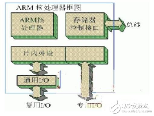
Figure 1 (ARM core processor block diagram)
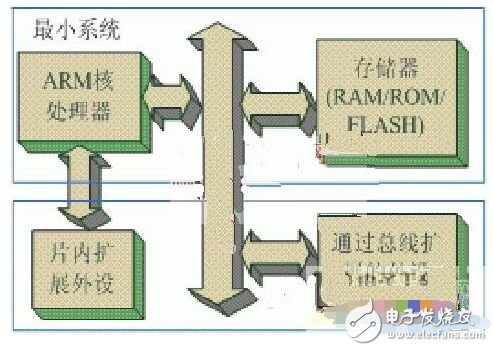
Figure 2 (Block Diagram of Embedded System for ARM Core Processor)
2.2 Implementation of an ARM-based Rapid Prototyping Platform
Figure 2 is a block diagram of an ARM-based embedded system. The system is divided into two parts, one part is the smallest system, which consists of embedded ARM core processor and memory; the other part includes peripherals that are directly extended from the embedded processor's on-chip peripheral interface and peripherals that are extended through the bus. In order to make full use of the modular design method, these parts should be able to form a platform through flexible interconnection. The flexible interconnection function is completed by the interconnection module.
Programmable devices such as CPLDs and FPGAs can be programmed in the system. Modifying the connection only requires modifying the corresponding control program, which is very convenient and flexible. CPLD is low in cost and fast in operation, but its integration is relatively low. The high degree of integration of the FPGA enables complex logic functions that are difficult to implement with CPLDs, such as built-in logic analyzer programs, obtaining the necessary signals, and completing the system on-line test. Another advantage of FPGA is that it can be configured dynamically. For example, when the system is powered on, the self-checking program is configured. After the self-test passes, the actual working program is configured. Finally, the CPU soft core is embedded in the FPGA to develop the SOC. Therefore, the programmable interconnect module is composed of FPGA.
In order to determine the insertion position of the programmable interconnect module, the structure of the embedded system of Figure 2 is analyzed.
The minimum system determines the processing capacity of the entire system and is the core of the entire system. The clock cycle of the commonly used embedded processor has already reached 400MHz, and will further develop. The bus speed connecting the processor and the speed of the memory chip also exceed 100 MHz. The FPGA pin-to-pin delay is on the order of a few nanoseconds, so inserting the FPGA module will slow down the entire system. Therefore, no FPGA module can be inserted between the processor and memory. Peripherals enable the embedded system to communicate and interact with the actual application environment. Usually the peripherals are already highly modular and independent, there is almost no requirement for flexible connections between the peripherals, and the data communication speed between the processor and the peripherals is much slower than that of the minimum system. Therefore, it is feasible to replace the direct physical connection between the minimum system and the peripheral with the interconnect module.
According to this idea, a rapid prototyping platform as shown in Figure 3 was designed.
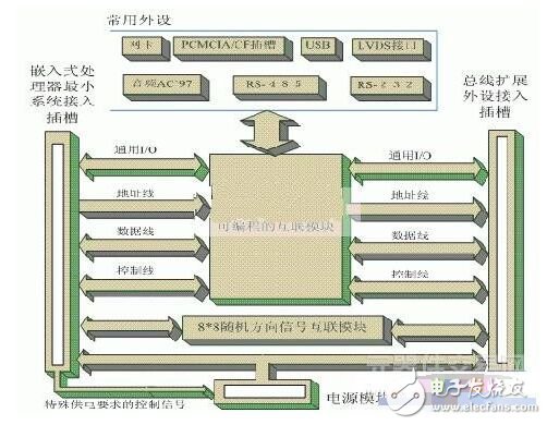
Figure 3 (rapid prototyping platform)
In Figure 3, the programmable interconnect module is the core part of the rapid prototyping platform. Common peripheral parts include: network card, USB interface, LVDS interface, RS-232 interface, rs-485/'target='_blank'>RS-485 interface, audio AC'97 interface, PCMCIA/CF card interface. These common peripherals are the reusable modules mentioned earlier. Since the bus, general I/O, dedicated I/O, and various peripherals of the embedded processor are all connected to the programmable interconnect module, different embedded processors only need to design the minimum system, and then the Minimal system access to the rapid prototyping platform, using the peripherals provided by this platform for system debugging.
The above-mentioned rapid prototyping platform not only considers the development characteristics of current embedded hardware systems, that is, there are many types of embedded processors, there are relatively few types of peripherals, interface standards tend to be unified, and at the same time, they fully embody testability and flexibility. Sexual, modular design ideas.
3 Configurable interconnection of random direction signalsThe common direction of signal transmission, whether one-way or two-way, can be predetermined. For example, the data bus is bidirectional, and read or write is completely deterministic, and the direction of data transfer can be controlled by reading and writing signals. But there is a special kind of bus, such as I2C, which is a multimaster/slave communication bus. As shown in FIG. 4, if the device 1 initiates communication, the signal transmission direction on the SCL is from device 1 to device 2. If device 2 initiates communication for the master device, the signal transmission direction on the SCL is just the opposite. System design requires two-way transmission of signals on the bus. The FPGA is internally composed of a series of logic gates. If the I2C signal is connected through the FPGA, it cannot work normally. This is because the bidirectional transmission can be regarded as equivalently implemented by two anti-parallel gates (as in Figure 5, the actual transmission direction is determined by the directional control signal). However, the I2C signal, without a clear direction control signal, cannot pass through the circuit of the structure shown in FIG. 5 correctly.
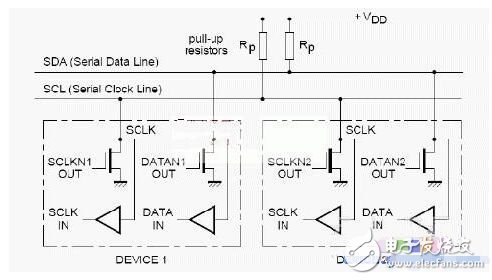
Figure 4 (I2C bus)
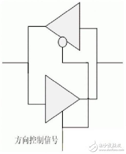
Figure 5 (bidirectional signal transmission)
If I2C signals are directly wired or jumpered, I2C can be guaranteed to work. However, this violates the flexibility of the configurable interconnection of the rapid prototyping platform. Therefore, the following solutions are proposed. The I2C signal is not configured to connect through the FPGA, but through MOSFET-based data switching. At present, commonly used point-to-point MOSFET switches in the market cannot be used directly. Because the common structure is one way to multiple or multiple to all the way. Using a CPLD to control the gating, multiple parallel connections can be made into 8x8 point-to-point, randomly configurable connections. The internal structure of the data switch is all the way to eight.
LCD drivers use FrameBuffer technology, so LCD drivers are also known as FrameBuffer drivers.
Liquid Crystal Display Monitor is a Liquid Crystal Display with a monitoring BNC signal processing terminal using a 7*24 hours professional power module and a monitoring driver scheme using Liquid Crystal Display technology.
contrast
Contrast, as opposed to brightness, is the main measure of an LCD monitor. Generally, the contrast ratio of Shanghai shadow display reaches 350:1, which can satisfy the function of normal display of computer, TV and other images; For the monitor LCD monitor, because the product itself has high requirements for the image, the general LCD monitor will sacrifice color parameters to improve the contrast and brightness of the whole machine.
So in general, use LCD monitor to see TV color effect is not as good as LCD TV, but LCD monitor contrast, clarity, brightness will be much higher than LCD, LCD TV.
resolution
Resolution refers to the number of horizontal and vertical liquid crystal lines on the LCD screen. Resolution is the most important index to evaluate a LCD monitor. We are talking about the physical resolution of the LCD monitor, not the maximum resolution that can be achieved.
LCD driver
Liquid crystal drive program, namely liquid crystal display drive board actually. Select different driver board, there will be different display effect. What general TELEVISION USES is TV 3 in 1 board. Support VGA, S terminal, AV signal. This kind of board mainly pays attention to the overall display color and saturation, resolution generally adopts standard 1366*768. So the LCD monitor modified by TV is relatively good when connected with TV signal.
Open Frame Lcd,Open Frame Touch Screen,Open Frame Lcd Monitor,Open Frame Touch Screen Monitor
Shenzhen Zhenniu Technology Co., Ltd , https://www.tydisplay.com