With the development of power electronics technology, microelectronics technology and AC servo control theory, AC servo drives have performance comparable to DC servo drives, and AC servo drive technology has been widely used in printing, CNC machine tools, food packaging, textiles , Plastics, electronic semiconductors and other industries. The motors of the AC servo drive system are generally divided into AC permanent magnet synchronous motors and squirrel cage AC asynchronous motors. AC permanent magnet synchronous servo systems have certain advantages in the small power range, but in high-power servo systems, squirrel cage asynchronous motors It is widely used due to its simple structure, easy manufacture, low price, wide application range and large flow capacity. The author has developed a set of squirrel cage three-phase asynchronous motor servo system based on ASIPM, field programmable logic gate array (FPGA) and dedicated digital signal processor (DSP). This article introduces the system control principle, hardware and software design , It was verified through experiments.
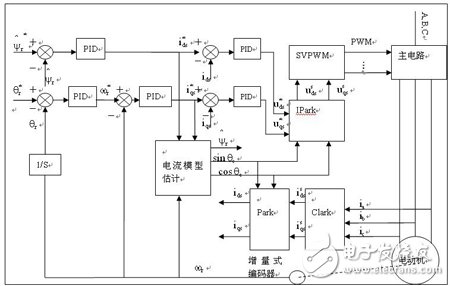
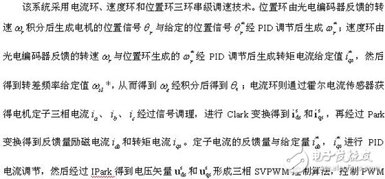
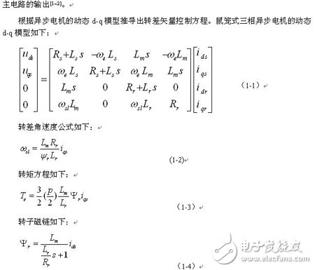
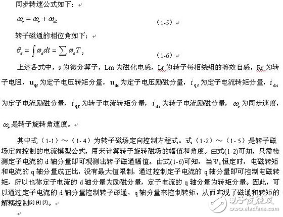
1 System control principleThe vector control of induction motors is usually oriented according to the stator flux linkage Ψs, rotor flux linkage Ψr and air gap flux linkage Ψm; according to the different ways of detecting the flux linkage position, vector control can be divided into direct vector control and indirect vector control. The system adopts the indirect vector control that is oriented to the rotor flux Ψr and uses the slip relationship to estimate the position of the flux relative to the rotor, and realizes the decoupling of the motor stator current by using coordinate transformation; Current model estimation is to estimate the sum of the rotor flux components using the speed signal and the current signal.
The system control block diagram is shown as in Fig. 1.
The hardware of the servo system with DSP as the core is shown in Fig. 3. The core of the control circuit of the whole system is composed of DSP + FPGA.
2.1 Main control circuit
Among them, FPGA, model XC3S400 of Xilinx, is mainly used for logic control of signals and output control of switch drive signals. The DSP model is TMS320F2812. As the control core, it controls the working parameters of the servo system after receiving the external signal, and converts it into the switching signal output of the inverter. After the signal passes through the isolation circuit, it directly controls the ASIPM module to supply power to the motor.
2.2 Power circuit
The entire main circuit first undergoes uncontrolled rectification, and then is output through a full-bridge inverter. The integrated intelligent power module (ASIPM) PS12036 of Mitsubishi Corporation is used in the power conversion circuit. The module uses a 15A, 1200V power tube, an integrated drive circuit, and is designed with fault detection and protection circuits such as short-circuit, over-current, and under-voltage. The system power supply adopts transformer step-down isolation diode rectification and filtering, and linear stabilized power supply and switching power supply provide power for each part, mainly including DSP and FPGA. Current sampling and processing circuit, photoelectric encoder interface circuit, 7-channel PWM signal drive Power supply, serial port circuit and protection circuit.
2.3 Current sampling circuit
The design of this system requires sampling of three-phase currents. The sampling circuit adopts Hall sensors and is limited to a voltage range of 0V~3.0V by AD analog circuit, and then sends it to the AD converter of DSP.
2.4 Rotor speed position detection circuit
Motor feedback adopts incremental photoelectric encoder, the encoder resolution is 2000 lines/revolution, output pulse signal A, B, Z, signal A, B phase difference in order of 90° (electrical angle), DSP judges A, B The direction and speed of the motor can be obtained by the phase and number of the motor. The Z signal appears once every revolution and is used to reset the position signal. The pulse signal of the photoelectric encoder disc is sent to the DSP after the isolation level conversion of the interface circuit, and the quadruple frequency is realized by the internal QEP circuit, so the number of pulses per revolution of the motor is 8000 lines/revolution.
3 System software implementation schemeThe software of this system can be divided into main program and PWM interrupt service subroutine in structure. The main program only completes the initialization task of the system hardware and software, and then is in a waiting state. The complete field-oriented real-time vector control algorithm is implemented in the T1 timer underflow interrupt service routine.
The sampling of the position speed uses the QEP unit of the DSP, and adopts the variable period sampling for the stability of the motor speed. The sampling period of different speed sections is different. Current sampling utilizes the AD conversion module that comes with TMS320F2812, and performs digital filtering on the signal at the same time. The current loop and the speed loop use PID regulators; in order to achieve rapid position following and no overshoot, the position loop uses a variable-ratio regulator. Space vector PWM (SVPWM) divides the rotor magnetic field space into 6 regions according to the switching logic of the inverter, and decomposes the stator voltage vector in each region to obtain the parameters required to generate the actual PWM waveform.
In order to improve the display range of numbers and the accuracy of calculations, and enhance the portability of the program, the calculation amount is standardized, which is to compare the calculation amount with its maximum or rated value, so that the budget is reduced to decimals, in order to satisfy The fixed-point arithmetic requirements of TMS320F2812 use _iq() in the IQmath library to convert decimals into integer forms, that is, the Q format of decimals [5]. In this way, floating-point operations are converted to integer operations that are much faster.
4 Experimental results and conclusionsIn this experiment, ASIPM uses Mitsubishi's PS12036, the experimental motor has a rated power of 2.2kW, a rated line voltage of 380 V, a rated frequency of 50 Hz, a rated current of 4A, and a Y-type connection. The carrier frequency of the SVPWM wave is 10kHz. The experimental waveforms are shown in Figure 7 and Figure 8. These waveforms verify the correctness of SVPWM, and the harmonic components of the inverter output current are reduced, indicating that the system has high control accuracy and good dynamic and static characteristics.
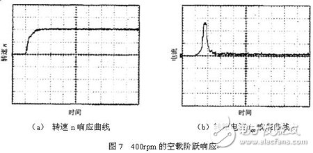
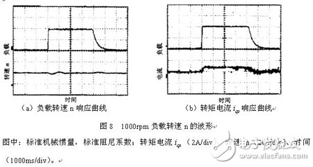
The AC servo system studied in this paper makes full use of the peripheral circuits and control interfaces of DSP and FPGA, which simplifies the hardware design. At the same time, the modular method is used in the software design to facilitate the writing of complex programs. The experimental results show that the system has good control performance. With the increasing demand for high precision and high reliability in industrial production, the application of AC servo systems will become more and more extensive.
IP67 Aluminium Case Led Driver
IP67 Aluminum Case Led Driver
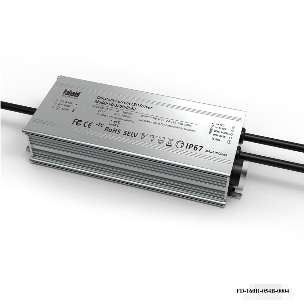
A comprehensive range of IP Rated/Waterproof AC/DC long life span led driver suitable for use in a range of Lighting applications, including Street lighting, Architectural Lighting, Task Lighting, Medical Lighting, Transportation Lighting, Entertainment Lighting, Moving Signs, Safety & Security Lighting and Outdoor Area Lighting Applications. LED Lighting power supplies & LED Drivers in constant voltage or constant current models IP67 rated. waterproof led driver,48V led driver.
Advantage: High Power Led Driver, safety and stability, high pressure test protection, short circuit protection, anti-lightning strong, safe level Certification, UL TUV FCC, etc. certification.
Parameter:
Input ovltage:100-277V
Output voltage(different range):24-38V/30-42V/36-54V/45-76V/72-143V
Current:100-5000mA
Power factor:>0.95
THD:<15%
Dimming: 0-10V/PWM/RX
Housing: Aluminum
What's the benefits of Fahold Linear Lights driver?
- Standard Linear Lighting
- Cost-effective light-line solution for industry,commercial and other applications
- Good quality of light with 5years warranty, EMC, EMI, safety SELV design
- Easy to order and install,requiring less time,reducing packaging waste and complexity
- Flexible solution
Question 1:Are you a factory or a trading company?
Answer: We are a factory.
Question 2: Payment term?
Answer: 30% TT deposit + 70% TT before shipment,50% TT deposit + 50% LC balance, Flexible payment
can be negotiated.
Question 3: What's the main business of Fahold?
Answer: Fahold focused on LED controllers and dimmers from 2010. We have 28 engineers who dedicated themselves to researching and developing LED controlling and dimming system.
Question 4: What Fahold will do if we have problems after receiving your products?
Answer: Our products have been strictly inspected before shipping. Once you receive the products you are not satisfied, please feel free to contact us in time, we will do our best to solve any of your problems with our good after-sale service.
Waterproof Led Driver,Long Life Span Led Driver,48V Led Driver,led constant current driver,driver for led light
ShenZhen Fahold Electronic Limited , https://www.fahold.net