Switching power supplies generally use pulse width modulation (PWM) technology, which is characterized by high frequency, high efficiency, high power density and high reliability. However, because its switching device operates in the high-frequency on-off state, the high-frequency fast transient process can complete the normal energy transfer, but it is a source of electromagnetic disturbance. The EMI signal it produces has a wide frequency range and a high amplitude, which can seriously affect the normal operation of other electronic devices.
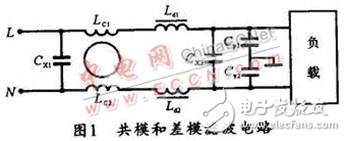
1 EMI filter circuitThe main performance of the switching frequency and its harmonics of the switching power supply is the interference on the power line, called conduction interference. Conducted interference is divided into common mode interference and differential mode interference. Common mode interference is caused by the potential difference between the current-carrying conductor and the earth. It is characterized in that the interference signal voltages on the two lines are in phase with the same potential; and the differential mode interference is the potential difference between the current-carrying conductors. The characteristic is that the interference signals on the two lines have the same potential but opposite phases. In fact, for different interference signals, the EMI filter circuit is also divided into anti-common mode interference filter circuit and anti-differential mode interference filter circuit. Figure 1 shows its filter circuit.

In Fig. 1, LC1, LC2, Cy1, and Cy2 constitute a common mode filter circuit. LC1 and LC2 are common mode filter inductors, while Ld1, Ld2, Cx1, and Cx2 form a differential mode filter circuit, and Ld1 and Ld2 are differential mode filter inductors. In this filter circuit, common mode filter inductor and differential mode filter inductor play a decisive role, its performance directly determines the success or failure of EMI filter, and the performance of common mode filter inductor and differential mode filter inductor is mainly caused by The characteristics of the core are determined, so the analysis of the core characteristics used in the EMI filter is of great significance.
In general, magnetic materials can be classified into soft magnetic, hard magnetic, magnetic pressure, etc. according to their characteristics and applications. Soft magnetic applications are the most widely used, and almost all inductive devices (inductors, transformers, sensors, etc.) are inseparable from soft magnetic materials. At present, the magnetic core with the most application of the filter inductor is also a soft magnetic material. In addition to the correct choice of magnetic parameters (such as Bs, μi, Tc), the choice of magnetic materials should be carefully selected for their electrical characteristics (such as resistivity, bandwidth, impedance, etc.). According to the characteristics of the EMI filter, the core selection of the common mode filter inductor and the differential mode filter inductor should comply with the following points:
First, the initial permeability is high (μi "2000);
Second, there must be a low coercive force Hc to reduce the hysteresis loss;
Third, the resistivity Ï is high to reduce the eddy current loss at high frequencies;
Fourth, ωc should be high, and the appropriate cutoff frequency can broaden the frequency band;
Fifth, Tc should be high to adapt to various working environments;
Sixth, there should be a specific loss frequency response curve, so that the loss is large in the frequency band where the EMI signal needs to be attenuated, so that the EMI can be attenuated to the lowest level, and the loss should be in the frequency band in which the signal needs to be transmitted. Small, so the signal is easy to pass.
2 common mode inductor coreThe frequency range in which the EMI filter needs to be suppressed is typically between 10 kHz and 50 MHz. In order for the common mode filter circuit to provide proper attenuation over this frequency range, the impedance of the core in this frequency range must be high. The total impedance (Zs) of the common mode core is composed of a series inductive impedance (Xs) and a series resistive impedance (Rs). In the low frequency part, the core impedance is mainly inductive impedance. As the frequency increases, the resistive impedance gradually increases and gradually plays a major role. Figure 2 shows the relationship between frequency and impedance. In the figure, the combination of the two impedances allows the core to provide a suitable total impedance (Zs) over this full frequency range.

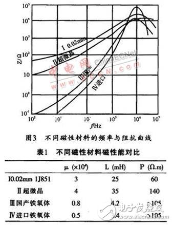
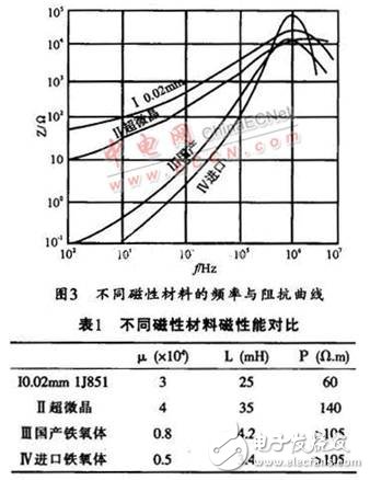
The common mode inductor coil is Lcl and Lc2 in Figure 1. Two sets of independent coils wound around a magnetic core have the same number of turns and opposite turns. Thus, when the EMI filter is connected to the circuit, the magnetic flux generated by the two sets of coils will cancel each other out in the core, so that the core will not be saturated. For the interference signal, the common mode core generally works in the low magnetic field region. Therefore, the magnetic material selected for the common mode filter inductor is required to have a high initial permeability μi. If only the insertion loss of the filter is used, the higher the initial permeability μi, the greater the inductive reactance exhibited by the filter circuit, and the better the insertion loss index is. However, in the whole circuit, other characteristics of the magnetic material in the circuit, such as frequency impedance characteristics, Curie temperature, shape of the magnetic material, and the like, are also considered. The magnetic properties of various magnetic materials with different μi values ​​are different at different frequencies, so it is necessary to select a magnetic material having a suitable μi value according to the required frequency range. Figure 3 shows the frequency versus impedance curves for different types of high μi soft magnetic materials under the same conditions. This curve reflects the change in insertion loss of the inductor core. Other performance parameters (such as inductance value, bulk resistance, etc.) are listed in Table 1.

In Fig. 3, curve IV is the impedance characteristic of an inductive core (Mn-Zn ferrite PC40) specially used for anti-common mode interference in foreign countries, and curve III is the impedance characteristic of domestic ferrite (R4 KB). . In the low frequency range (100 Hz to 10 kHz), due to the high resistivity of the material itself, the AC equivalent resistance is small, and the inductive reactance in the circuit plays a major role, indicating that the ferrite material has less inhibitory effect on the interference signal in this frequency band. . Ultrafine crystal (curve II) and metal magnetic material thin film alloy 1J851 (curve I) material because the material itself has a relatively low resistivity, the eddy current loss increases as the frequency increases, and its equivalent impedance Z is larger than that of ferrite. many. In the frequency range of 10 to 100 kHz, the Z of the four materials is increasing, but the slope of the change of the ferrite material is steeper than that of the ultrafine crystal (curve II) and the metal magnetic material thin film alloy 1J851, indicating that in this frequency band Within them, their suppression of interfering signals is constantly increasing.
Asic Power Supply,High Power Uninterruptible Power Supply,Active Computer Power Supply,4000W Computer Power Supply
Boluo Xurong Electronics Co., Ltd. , https://www.greenleaf-pc.com