1 Introduction
As the complexity of the design continues to increase, more resources are required to be verified. Not only does verification require coverage of all functions, but it also hopes to give a large number of exceptions to check the processing status of the DUT's corresponding exception. Test methods are often difficult to achieve. In addition, the design is constantly being reused, and verification also hopes to reuse the same verification module, which has led to a hierarchical verification method. Synopsys' VMM verification methodology provides SystemVerilog-based verification methods, including constrained random number generation, hierarchical verification structures, and verification processes with functional coverage metrics. In this paper, an MCU verification environment is built around Synopsys' VMM (VerificaTIon Methodology Manual).
2 DUT
In this environment, an 8-bit MCU is verified. The CPU clock cycle is the instruction cycle. It is compatible with the MCU instruction set and contains 8-bit arithmetic logic units. It contains commonly used registers such as ACC, B, PSW, and 4 groups of R0-R7. The R register supports direct, indirect addressing, and bit operations. The jump instruction can be an 8-bit signed relative address jump or an 11-bit, 16-bit unsigned absolute address jump.
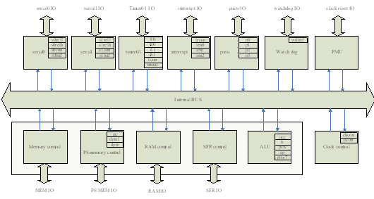
4 priority 12 interrupts, interrupts include external input interrupts, internal interrupts such as serial ports and counters, 15-bit programmable Watchdog, additional program ROM interface, external RAM interface, internal RAM and SFR interface. The MCU itself does not contain memory. All ROM and RAM communicate through an external interface. Here, a behavioral level memory model is implemented in the VMM environment to save program code and data. The following is a brief block diagram of the MCU.

Figure 1 MCU internal structure
This MCU also improves the instruction cycle on the original basis, reducing the instruction cycle required for most instructions to execute. Because the instruction cycle required by some instructions is shortened, many original sampling and assignment times change accordingly. On the basis of functional verification, it is necessary to pay attention to whether it affects the next instruction, especially the interrupt and some instructions occur simultaneously. Some special circumstances at the time.
The instruction execution of the MCU is realized by reading and writing RAM memory. In addition, all peripherals will start the corresponding function by configuring SFR memory, and will set the corresponding SFR to display the working result or state of the peripheral. Here RAM memory And the SFR memory content is the detection point that needs attention. As long as the RAM memory and the SFR memory contents are correct, all the functions of the MCU can be verified to be correct.
Intelligent Power Distribution Box
Intelligent power distribution box is a new type of power distribution device, with modular structure, fashinable and attactive appearance, and high protection class. It can be used alone or combined with other devices. The products are widely used for the lighting, power and loop control in airport, hospital, school, industrial and civil buildings.
Intelligent Power Distribution Box,Power Distribution Box Waterproof,Small Power Distribution Box,Small Power Distribution Box Waterproof
Jiangsu Sfere Electric Co., Ltd , https://www.elecnova-global.com