Since the charger sockets attached to each model phone are different, it is not common between the mobile phone chargers. When the user's mobile phone charger is damaged or lost, the same type of charger cannot be repaired or purchased, making the phone unusable. Universal charger manufacturers have developed such a business opportunity to develop and produce a universal charger for mobile phones. The charger is popular among users because of its small size, convenient carrying, simple operation, and low price. The following takes the Sihaitong S538 universal charger produced by Shenzhen Yalitong Industrial Co., Ltd. as an example to introduce its working principle and maintenance method. The charger has a high market share, and there is no random accompanying circuit diagram, which brings certain difficulty to the maintenance. This paper draws out the working principle diagram according to the physical object, see the attached drawings for reference during maintenance.
The Sihaitong S538 universal charger is unique in design. The panel is made of semi-elliptical clip made of transparent plastic. The transparent plastic panel is fixed with two adjustable stainless steel reeds as charging electrodes. There is a test switch (polarity switch) and 4 status indicators along the tail of the panel. The user can adjust the charger electrode distance and output voltage polarity as needed, and the battery status can be easily seen through the status indicator. .
First, the working principle
The charger circuit is mainly composed of an oscillation circuit, a charging circuit, a voltage stabilization protection circuit, etc., and its input voltage is AC220V, 50/60Hz, 40mA, the output voltage is DC4.2V, and the output current is 150mA~180mA. Before charging, first connect the battery to be charged, see if the test indicator on the charger panel is bright? If it is on, it means the polarity is correct, you can turn on the power and charge; otherwise, it indicates the polarity of the battery and the output voltage of the charger. The polarity is reversed, in which case you need to press the polarity switch AN1 (test button). The specific circuit principle is as follows.
1. Oscillation circuit
The circuit is mainly composed of a triode VT2 and a switching transformer T1. After the power is turned on, the AC 220V is half-wave rectified by the diode VD2 to form a DC voltage of about 100V. The voltage is applied to the c-pole of the transistor VT2 via the primary winding of the switching transformer T, and the voltage is supplied to the b-pole of VT2 via the starting resistor R4 to provide a forward bias voltage to turn VT2 on. At this time, the intermittent oscillation circuit composed of the transistor VT2 and the switching transformer T1 starts to operate, and a current flows through the 1-1 primary winding of the switching transformer T. Due to the positive feedback function, the voltage induced in the 1-2 winding of the transformer T is applied to the b pole of the VT2 through the feedback resistor R1 and the capacitor C1, so that the b-pole conduction current of the triode VT2 is increased and rapidly enters the saturation region. As the voltage across the capacitor C1 rises, the b-pole voltage of VT1 gradually decreases, causing the transistor VT2 to gradually exit the saturation region, and its collector current begins to decrease, and the magnetic flux generated in the 1-1 primary winding of the transformer T also begins to decrease. The negative feedback voltage induced in the 1-2 winding of transformer T causes VT2 to turn off quickly, completing an oscillation period. During the VT2 entry cut-off period, the 1-3 winding of the transformer T induces an AC voltage of about 5.5V as the charging voltage of the latter stage.
2. Charging circuit
The circuit is mainly composed of a soft plastic integrated block IC1 (YLT539) and a triode VT3. The AC voltage induced from the 1-3 winding of the transformer T is 5.5V, rectified by the diode VD3, filtered by the capacitor C3, and output a voltage of about 8.5V DC (at no load), and this voltage is partially added to the e pole of the triode VT3. The other part is sent to the 1st leg of the soft plastic integrated block IC1 (YLT539) to provide working power. The integrated block IC1 starts working after having the working power supply, and outputs a low-level charging pulse at the 8th pin, so that the triode VT3 is turned on, and the DC 8.5V voltage starts to charge the battery E.
When the voltage of the battery to be charged is lower than 4.2V, the voltage is divided by the sampling resistors R11 and R12, and then applied to the 6th pin of the integrated block IC1, the voltage is lower than the internal reference voltage of the integrated block IC1, the integrated block The lower the level of the 8-pin output of IC1, the lower the b-pole potential of the triode VT3, and the larger the conduction amount, the DC voltage (8.5V) is quickly charged to the battery E via the polarity switching switch S1. Since the 2, 3, 4 pins of the integrated block IC1 and the capacitor C4 together constitute an oscillating resonant circuit, the oscillating pulse of the 2-pin output is sent to the positive pole of the charging indicator LED1 (green) via the resistor R16, and the negative pole thereof is connected to the integrated block IC1. 8 feet. When the battery is just connected to the circuit, the lower the level of the 8-pin output of the integrated block IC1, the charging indicator LED1 flashes brightly. As the charging time is prolonged, the voltage charged by the battery gradually rises, and the output voltage of the 8-pin of the integrated block IC1 gradually rises, and the charging indicator LED1 flashes gradually and becomes weaker.
When the battery E is slowly charged to about 4.2V, the potential of the 6-pin of the integrated block IC1 also reaches its internal reference voltage of 1.8V. At this time, the internal circuit of the integrated block IC1 operates to make its 8-pin voltage output high level, the triode VT3 is turned off, the charging indicator LED1 is no longer flashing and extinguishing, and the full-fill indicator LED2 (green) is turned off.
3. Voltage regulator protection circuit
The circuit is mainly composed of a triode VT1, a Zener diode VDZ1 and the like.
Overvoltage protection: When the output voltage rises, the voltage induced at the 1-2 feedback winding end of the transformer T rises, and the voltage charged by the capacitor C2 rises. When the voltage across the capacitor C2 exceeds the voltage regulation value of the Zener diode VDZ1, the Zener diode VDZ1 breaks through, and the base voltage of the transistor VT2 is pulled low, so that its conduction time is shortened or rapidly turned off, and coupled via the switching transformer T1. After that, the secondary output voltage is lowered. Conversely, the output voltage is raised to ensure that the output voltage is stable.
Overcurrent protection: When the power is turned on or when the current of the transistor VT2 is too large for some reason, the voltage drop on R5 and R6 is large, so that the overcurrent protection tube VT1 is turned on and VT2 is turned off, thereby effectively preventing the switch. Tube VT1 is damaged due to excessive surge current. At the same time, the voltage drop across the resistor R6 causes the voltage across the capacitor C2 to rise. After that, the overcurrent protection process is the same as the voltage regulation principle and will not be repeated here. Transistor VT1 is an overcurrent protection tube, and R5 and R6 are VT2 overcurrent sampling protection resistors.
Second, common troubleshooting
Example 1: After the battery and power supply are connected, the power PW indicator LED3 and the test indicator TEST LED4 are on, while the charging LED1 and the full-charge indicator LED2 are not lit, no voltage is output, and the battery cannot be charged.
Analysis and repair: This kind of fault is mostly caused by the charger switching oscillator circuit not working. During the actual maintenance process, it was found that the switch tube VT2 and the resistor R6 were the most damaged. Under normal circumstances, the charging circuit of the battery E has a low operating voltage, and the probability of component damage is not very large, that is, the probability of damage of the circuit after the secondary of the switching transformer T1 is not large.
Example 2: After the battery and power supply are connected, the status indicators are normal, but the charging is not charged or the charging time is long.
Analysis and repair: This kind of fault is mostly the damage of the triode VT3 (8550). After replacing it with a normal pipe, the fault can be eliminated. If the triode VT3 is normal, use the meter to measure the voltage across the capacitor C3 (100μF/16V), which is normally about 8.5V DC. If the voltage is normal, the resistor R7 or the integrated block IC1 should be checked. The normal parameters of the pins of the integrated block IC1 are shown in the attached table. If the voltage is low, measure the secondary output voltage of the switching transformer T1, which is normally about 5.5V AC. If the voltage is normal, the capacitor C3 or the rectifier diode VD3 is damaged. If the voltage is low, check the switching transformer T1 and its pre-stage components.
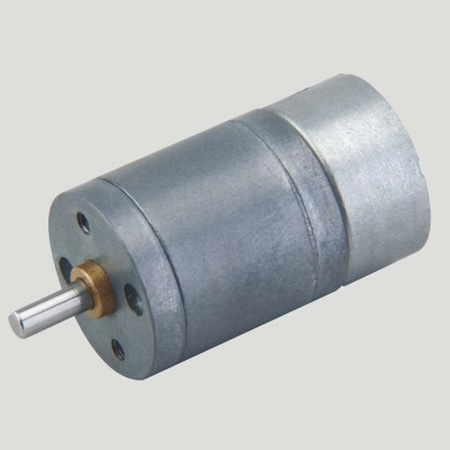
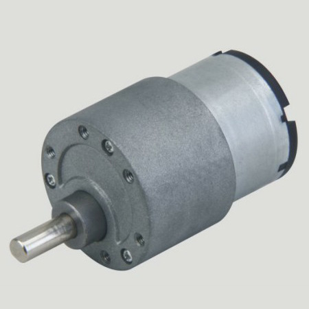
Permanent magnet Dc Motor is composed of stator magnetic pole, rotor, brush, case and so on. Stator magnetic pole is made of permanent magnet (permanent magnet steel), ferrite, alnico, ndfeb and other materials, and the rotor is generally made of silicon steel laminated. Enameled wire is wound between two slots in the rotor core (three slots are provided with three windings), and its joints are separately welded on the metal sheet of the commutator. Electric brush is a conductive part connecting power supply and rotor winding. Permanent magnet motor brush USES single metal sheet or metallic graphite brush, electrochemical graphite brush.Permanent magnet Gear Motor is established using permanent magnet magnetic field of a dc motor. Permanent magnet gear motor is widely used in various kinds of portable electronic equipment or apparatus


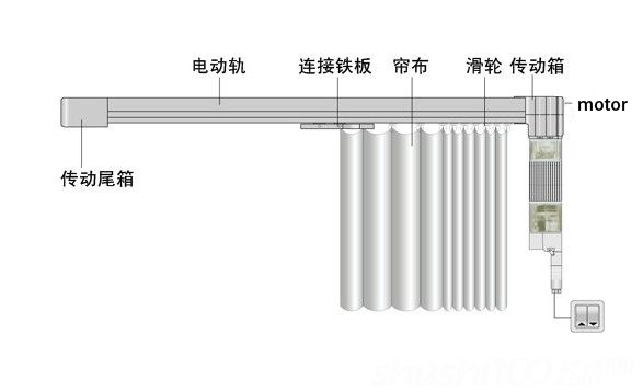
precision instruments and meters,automobile industry, medical equipment, consumer electronics, household appliances, electric glass doors and Windows,etc., wide application range,,Permanent Magnet Gear Motor is usually used in small power occasion.


Features: permanent
magnet gear motor is a kind of rectangular pulse wave, sine wave current, in the form of hybrid permanent magnet motor. Simple structure, high reliability and high efficiency.
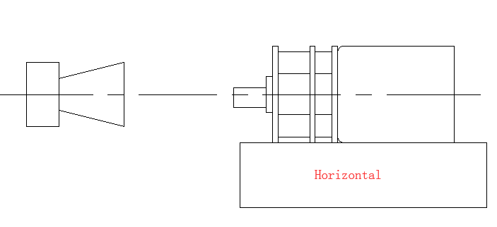
Method of use: the best stable in horizontal plane, installed on the permanent magnet gear motor output shaft parts, cannot use a hammer to knock,knock prone to press into the permanent magnet gear motor drive, may cause damage to internal components, and cannot be used in the case of blocked.

Operating temperature range:
permanent magnet gear motor should be used at a temperature of -10~60℃.
The figures stated in the catalog specifications are based on use at ordinary room temperature catalog specifications re based on use at ordinary room temperature (approximately20~25℃.
If a geared motor is used outside the prescribed temperature range,the grease on the gearhead area will become unable to function normally and the motor will become unable to start.Depending on the temperature conditions ,it may be possible to deal with them by changing the grease of the motor's parts.Please feel free to consult with us about this.
Storage temperature range:
permanent magnet gear motor should be stored ta a temperature of -15~65℃.
In case of storage outside this range,the grease on the gearhead area will become unable to function normally and the motor will become unable to start.
Service life:
The longevity of permanent magnet gear motor is greatly affected by the load conditions , the mode of operation,the environment of use ,etc.Therefore,it is necessary to check the conditions under which the product will actually be used .The following conditions will have a negative effect on longevity.Please consult with us should any of them apply.
â—Use with a load that exceeds the rated torque
â—Frequent starting
â—Momentary reversals of turning direction
â—Impact loads
â—Long-term continuous operation
â—Forced turning using the output shaft
â—Use in which the permitted overhang load or the permitted thrust load is exceeded
â—A pulse drive ,e.g.,a short break,counter electromotive force,PWM control
â—Use of a voltage that is nonstandard as regards the rated voltage
â—Use outside the prescribed temperature or relative-humidity range,or in a special environment.
â—Please consult with us about these or any other conditions of use that may apply,so that we can be sure that you select the most appropriate model.
when it come to volume production,we're a major player as well .each month,we rurn out 600000 units,all of which are compliant with the rohs directive.Have any questions or special needed, please contact us, we have the engineer group and best sales department to service to you Looking forward to your inquiry. Welcome to our factory.

Permanent Magnet Gear Motor,Permanent Magnet Motor With Gear,Permanent Magnet Gear Motor 5V,Permanent Magnet Stepper Gear Motor
Shenzhen Shunchang Motor Co., LTD. , https://www.scgearmotor.com