As my country's requirements for environmental governance are getting higher and higher, dust has become an important indicator of environmental monitoring. As an important part of the indicators affecting PM2.5 and PM10, dust in the air has also become the object of monitoring by environmental protection departments at all levels. . At present, the main methods of dust monitoring are manual sampling and analysis. The detection efficiency is low and a lot of manpower and material resources are wasted. Aosen self-developed all-weather outdoor dust monitoring system can not only realize dust monitoring, but also monitor PM2.5, PM10, noise, air temperature, air humidity, wind speed, wind direction and other environmental factors. The test data of each monitoring point has passed The wireless communication is directly uploaded to the background of relevant departments, which greatly saves the monitoring cost of the regulatory department and improves the monitoring efficiency.
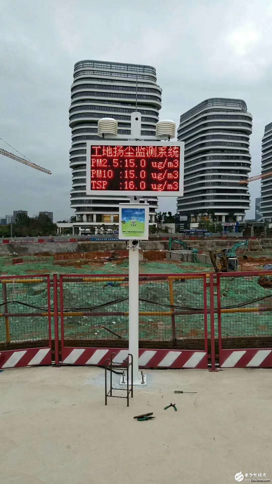
So, how to install the dust and noise pollution monitoring system? Shenzhen Aosen Purification Technology Co., Ltd. dust and noise monitoring manufacturer provides you with detailed installation methods:
1. Confirmation of installation point
The installation point must have a 20cm thick cement hardened ground or a built-in part (pre-embedded part method) to provide a stable voltage AC220V power supply.
2. Installation of pole
l Connect the two poles first, lock the screws, and observe whether they are vertical (if not vertical, put a little iron piece).
l Install the lightning rod and observe whether it is vertical (if it is not vertical, straighten it by hand).
Open the wiring door with a tool.
3. Installation of the sensor
Fix the short cross arm and long cross arm with hoops above the holes 1 and 2 respectively;
Fix the wind speed sensor and the direction sensor (the wind direction should be roughly to the south, use the compass to determine the direction) respectively with screws on both ends of the short cross arm, insert the end of the unlabeled aviation connector cable at the bottom of the sensor and lock it. Pass the wire in along the cross arm port, and then use the lead wire to lead the aviation connector line from hole 1 to the hole; connect the two louver sensors to the corresponding aviation connector line (the unlabeled end is connected to the sensor) from the cross arm Pass through the port and lock the sensor, then fix the two ends of the long cross arm with screws, pass the wire along the cross arm port, and then use the lead wire to lead the aviation connector line from hole 2 to hole 4;
4. Screen installation
Fix the LED screen with a hoop between hole 2 and hole 3. The power cord of the screen enters hole 4 from hole 3,
5. Installation of the main box
Fix the main box with a hoop between hole 3 and hole 4.
6. Wiring of the main box
l Locate the two-core power cord attached to AC220V, pass it in from the bottom and connect it to the load terminal on the leakage switch in the chassis.
l The wires passing through hole 4 are inserted into the aviation interface one by one according to the label instructions, and the antenna is attached to the chassis.
7. Fixing of equipment
Move the equipment to the installation point, stand it up and punch it with an electric hammer, and fix it with 16*200mm expansion bolts.
8. Wiring method of AC220V
Open the low-end wiring door cover of the pole, pass the AC220V two-core wire of the chassis from hole 4 into the wiring door and connect it with the externally powered AC220V, and wrap it with tape. The external power supply line should be a three-core wire, one of which To be grounded.
9. Confirm the normal operation of the equipment
l Open the case, turn on the leakage switch, wait for 1-2 minutes, there will be a long beep in the case.
l When the case keeps beeping, observe the screen at the same time. A line of version information will appear on the screen (the version information may not be upgraded to 6.3). The device will work normally after the version information disappears. During normal operation, the detected data will change (if dust Unchanging can create dust, such as: spit a smoke or sprinkle some dust next to the sensor, noise can create noise, such as: clapping hands or hitting objects that are easy to make noise, and wind speed and direction can be changed to rotate the wind speed and direction sensor, above The method can detect whether the device is working normally), when the device detection parameter is greater than 3 items, it will switch cyclically.
DB25 Female Connector, DB25 Male Connector,DB9 Male Connector,DB9 Female Connector,DB9 Right Angle Backshell,Molded D-Sub Cables
The On-site injection molding enables us to custom mold your D-Sub assemblies to your specs with logos. We are tooled for:
DB9 molded cables,,DB25 molded cables, DB50 molded cables, HD15 molded cables
DB Backshell or Boot-Kit Cables: The backshell cans and boot-kits are available for D-Sub DB15 cablesD-Sub DB37 cables.
Backshells are offered for: D-Sub high-density HD26, HD44, HD62, HD78
D-sub cable, DB cable, 9pin DB cable, molded DB connector, Data Cable
ETOP WIREHARNESS LIMITED , https://www.oemwireharness.com