As we all know, when the output terminal of the power supply exceeds the rated load or is short-circuited, it will damage the power supply and even cause the system to fail to work normally. In view of this, we must carry out the current-limiting protection design for the product when designing the power supply. Then there are many ways, we can design it to the input end of the power supply or design it to the output end of the power supply. To achieve the best design method depends on the actual situation, the following methods are commonly used current control methods:
1) The power supply of the primary reference direct drive mode can be designed to the input terminal, as shown in the figure below
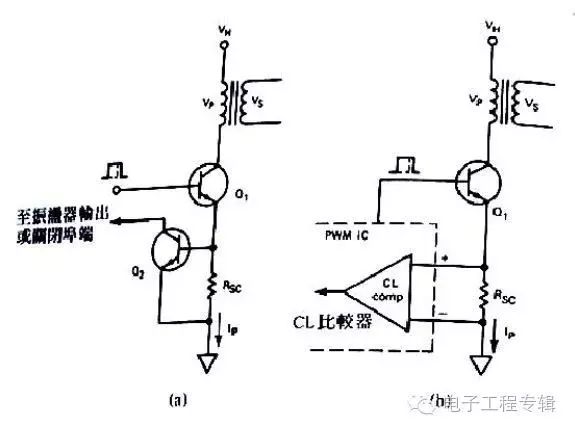
The working principles of the two circuits in the figure are: (a) Figure: When an overload or short circuit occurs at the output, the primary current will increase quickly at this time, and a voltage will be generated on Rsc, which exceeds the conduction of BE If the voltage is turned on, Q2 will be turned on and the collector potential of Q2 will be pulled to the ground. If it is connected to an oscillating circuit, it will cause the oscillating circuit to stop working, thereby achieving the purpose of protection.
The value of Rsc is: Rsc=Vbe/Ip
(b) The circuit in the picture is a commonly used current-limiting protection circuit, which is welcomed by designers in counterattack or forward circuits. His working process is somewhat similar to that in Figure (a), but it has some good advantages. First, the current limit excitation threshold voltage of the comparator can be prefabricated to an accurate and prefabricated level. It is equivalent to the threshold voltage value of the bipolar transistor with a larger Vbe voltage range, and the second is that the threshold voltage is small enough, basically 100MV and 200MV, so the current limit battery group can be smaller, which can improve efficiency .
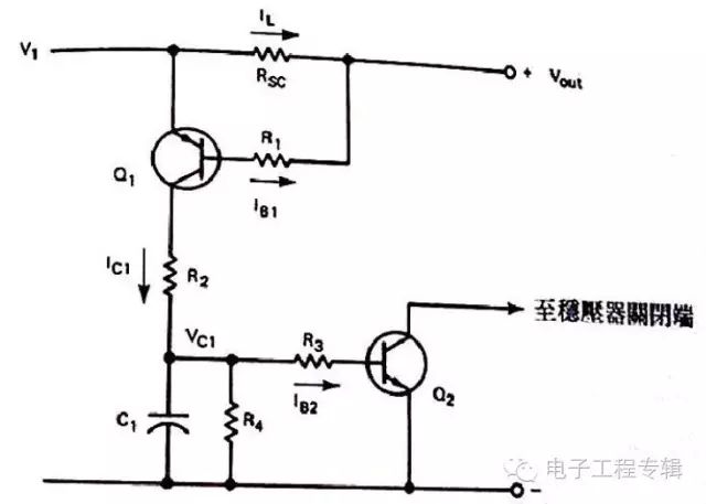
2), the current limit circuit applied to the base driver
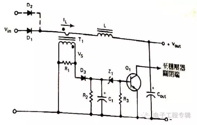
Since IR=VS/R1, in the case of the maximum specified load current IC, the number of secondary turns must be able to produce the desired voltage value on the capacitor C1, so NS=NP*IRR1/(Vs+Vd3) So far we can A precise transformer is wound, and the number of turns must be slightly adjusted in the actual circuit test in order to achieve the best performance. There is also a current limiting circuit: as shown in the figure, it can achieve good results whether it is placed on the input end or the output end of the power supply. The same circuit can also be suitable for multi-output power supplies, but there are One point, it takes a lot of effort to achieve the effect of each current limit for multiple sets of output.
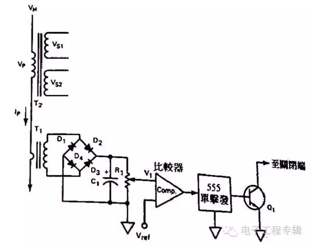
The working principle of the above figure is: T1 is used to detect the primary current of T2, after T1 is rectified by a diode, the capacitor is filtered, and the variable resistor R1 is used to set the threshold voltage at the input of the comparator. In the positive long working condition, the comparator The Vref reference input voltage will be higher than the voltage on the electric guard R1, and the output of the comparator will be at a high level. At this time, the 555IC (single-excited multivibrator) will have a low-level output, so Q1 remains closed. If an overload occurs, the voltage V1 will be higher than VREF, so that the comparator is at the bottom potential. The conversion process of the IC555 input terminal from high potential to the bottom potential will produce a single-shot output at the IC555 output terminal, and turn Q1 ON, C pole It is connected to the closed input terminal or the soft start capacitor of the PWM circuit, so it will be pulled to the ground level. The output conversion pulse is terminated and the regulator is turned off. If the overload condition continues, the power supply will be in a hiccup state, that is, it will be between the ON and OFF states with the period of the IC555 single-excited RC time constant. Stopped conversion, the circuit will not return to the normal state until the overload is removed. The transformer design is the same as the previous section.
2.0mm Pitch
2.0mm Pitch
ATKCONN ELECTRONICS CO., LTD , https://www.atkconn.com