This article discusses grounding issues in automobiles. First, review the composition of typical automotive grounding systems, the functions they are to implement, and the drawbacks known to date. Some sources of radiation on the car are listed and the role of grounding to reduce these emissions is discussed.
1 OverviewSince the use of electrical energy for ignition in 1860, cars have begun to transmit electromagnetic disturbances to the surrounding electromagnetic environment. Today's cars, especially engine ignition systems, face enormous challenges in electromagnetic compatibility. In the process of design, in order to ensure the coordination of various parts of the car, compatibility with each other, to comply with various international, national and local electromagnetic compatibility standards, in addition, EMC engineers must also consider passenger comfort, including radio entertainment equipment, car phones , GPS, explosion-proof devices (radar and lidar), and other advanced equipment that will be applied to later functional vehicles.
The "ground" in automotive electronic systems does not only play a role, the term is often used to refer to some automotive conductors, which have the following functions:
1 Provide a current loop
2 Provide reference voltage for analog sensors and digital logic circuits
3 Grounding network for FM and AM antennas
4 for shielding RF bypass current
5 electrostatic protection
This paper reviews the factors affecting the grounding of the vehicle system and illustrates the role of some key factors.
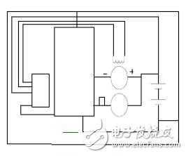
2 Automotive Grounding System 2.1 OverviewAs shown in Figure 1, the vehicle power supply consists of a battery, a generator and an elegant regulator. It is the power system of the automotive electrical system, providing sufficient electrical power and stable operating voltage for the automotive electrical system. The vehicle power supply is powered by the battery and the generator in parallel. When the generator is running, its output current drives the DC load, but the internal capacitance of the generator is too large, so it cannot output a fast switching current. Then this task has to be done by the battery.
In addition, the primary consideration for automotive grounding systems is to ensure that the starter operates correctly, so we must also consider the requirements of the starter. In order to ensure that the starter motor can operate in cold weather, its current loop must exhibit DC low resistance between the battery negative pole and the starter ground (generally the engine body). The mounting position of the starter and battery may create an additional unfavorable current loop between the ground conductors.
In the car, many components are dedicated to grounding, including body metal, engine body, wiring and batteries.
2.2.1 Body metal bodyAlthough body materials are now increasingly using composite materials or plastic panels, today's automotive bodies still use metal over a large area. Because of its size, shape and convenient layout (for example, close to most electrical equipment), body metal is unique in providing current loops, reference potential, shielding and noise attenuating. To design a good car grounding system, the goal is to maximize the role of the body metal body.
Due to its unique shape and large surface area, the body itself is a huge capacitor. It has been verified that the body metal body can absorb high frequency and small amplitude current. However, there is a common impedance coupling in doing so, especially when there is current passing through the joint on the body. In addition, if the body metal body is used as a general-purpose current loop, rather than doing certain current loops, it will not only be unable to exert its strengths, but will add an important source of radiation. The Ohio State University and the American Daimler-Chrysler Company have conducted experiments and found that if the body metal body only provides a loop for the general ignition current, the surface electric field is not stable and there is obvious interference burr. This is because the current passes through the car. The baffle creates noise in the radio entertainment device. If the car is added with a component that keeps the current loop away from the body metal body close to the baffle, the surface electric field is very stable.
The body metal body can also shield low frequency capacitors. In the case where the frequency exceeds kilohertz, since the body metal body itself has a certain thickness, it also exerts a certain electromagnetic shielding effect on the engine case. In addition, it is the main conductor for automotive and lighting systems, external ESD interference, and other sources of radiation outside the vehicle. However, if the body is of a general construction, this shield cannot achieve reliable electrical integrity. The connection between the metal plates may be by solder joints, non-conductor anti-corrosion insert layers or non-conductive paint. Ideally, the fixed metal plates are electrically joined, and the movable metal plates (canopies and doors) are connected by auxiliary conductors (grounding bars). The body metal body should be connected to the battery negative through a strong low-impedance harness.
2.2.2 Engine body and cylinder headThere are a variety of electrical signals in the engine block and cylinder head. In addition to the possible conductive coupling between them, some signals can generate voltage between the engine unit and the body metal through the loop lead inductance. This voltage can generate radiation or capacitive coupling to electronic devices within the engine.
The engine and cylinder head are physically tightly connected by a number of large diameter bolts, but the electrical characteristics of the joint are generally poor. Cylinder head gaskets are often insulated and often have inferior conductors on the outside. The connections between the engine block and other engine components, including the generator frame, valve cover, and throttle body, are uncontrollable and can change at any time during engine operation.
2.2.3 WiringDue to the large size of the engine and the components of the automobile, the grounding impedance is inevitably generated at high frequencies. Moreover, the distance between these components is large (on the order of meters), so the inductance problem of the current loop is also difficult to eliminate. In general, the inductance of the wiring reaches several tens of nH/inch, and the inductive capacity of many automotive parts can be on the order of μH. Then a few amps or more in an automotive system with a frequency higher than 100 kHz may cause a large voltage drop in the current loop.
2.2.4 BatteryIn addition to storing electrical energy, the battery can also suppress some noise. At low frequencies, lead-acid batteries exhibit a capacitive reactance of 1-2F per 100 Ah. When placed in parallel with the generator, this reactance will help reduce the low frequency noise generated by the car's charging system. In the high frequency state, the reaction inside the battery is more complicated. In the range of 25 kHz to 250 kHz, the battery exhibits capacitive (tens of nF) and does not substantially follow the frequency. It has been observed that the order of magnitude of the effective capacitance is related to the load state and size of the battery. In the high frequency state, the reactance of the equivalent battery is optimal with a series LC circuit. At this time, if the frequency is higher than 1 MHz, series resonance is likely to occur. Because of this, the battery cannot be applied to suppress the amplitude modulation broadcast band or higher radio frequency noise.
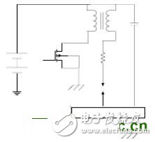
Figure 2 Schematic diagram of the ignition system
3 Automotive EMC issues to considerAccording to the above, the car itself has many sources of radiation and sensitive components. Due to space limitations, in this section we only discuss the more specific components in the automotive environment.
3.1 Ignition deviceThe primary and secondary ignition circuits of automobiles are the most common sources of emissions. Since the two stages of circuits are coupled by the ignition coil, their waveforms are completely different, which are separately described here.
The primary ignition circuit includes a current source (battery or alternator), an ignition coil, and a trigger (usually an engine controller). A schematic diagram of the current ignition system used in most cars is shown in Figure 3. For this type of circuit, the primary concern with EMC is the falling edge of the coil current waveform.
Figure 3 shows the current and voltage waveforms of the ignition coil primary. This part of the waveform contains effective high frequency energy (100KHz and above), which is affected by the inductance of the ground loop harness.
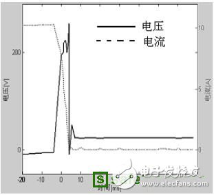
Figure 3 Voltage and current waveform of the ignition coil primary
The secondary ignition circuit includes an ignition coil, a spark plug, a cylinder head and other conductors. The equivalent circuit is shown in Figure 4. This circuit includes an engine block and an engine control module. It also includes a 1pH grounding inductance that can touch the engine block. And the control module has a potential difference of several volts for the battery. Here, the primary voltage is represented by an equivalent series voltage source. Although capacitance and radiation losses occur at sufficiently high frequencies, the current loop to the battery can be represented by an equivalent inductance; Cc represents the parasitic capacitance through the coil. In the figure, it is not seen that the secondary is capacitively coupled to the primary through the ignition coil. This actual coupling method can increase the radiation voltage and introduce more conductive coupling into the electronic system.
This problem can be alleviated if we minimize the area of ​​the closed loop and place the components reasonably to shorten the lead distance between them. In addition, in the current loop flowing through the negative electrode of the battery, no other conductor can be used as the reference potential, and the body metal body is not acceptable.
In automotive-generated signals, the secondary ignition circuit's signal is unique because its spectral range can be as high as about 1 GHz. It is therefore particularly likely to be a source of radiation, but its conductive coupling to other components of the engine is also a source of radiation.
Figures 2 and 4 show the generation mechanism of the high-frequency emission signal of the secondary ignition circuit. The battery supplies direct current to the primary winding of the ignition coil. The primary and secondary windings of the engine are constructed with an autotransformer. It takes a certain amount of time for the electronic switch in the engine controller to drive the primary winding. It is known that the multiple of the primary voltage is amplified by a turns ratio (generally several hundred), and a voltage of several tens of kV is generated in the secondary. Therefore, an RF suppression capacitor Crf is applied between the high side of the coil and the cylinder head.
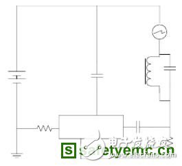
Figure 4 Ignition system secondary equivalent circuit
The spark plug RF characteristics can be described by the following model: (1) an equivalent arc impedance L, which can be used to describe a nonlinear time-varying current flowing through the spark gap, and (2) a metal sheath and internal iron threaded from the outside of the spark plug. A coaxial capacitor composed of a core. In fact, the spark gap is broken when the arc is not discharged, and we use a switch to indicate it. After the switch is closed, the capacitor Cp is quickly discharged through the gap.
3.2 Car Wireless Entertainment SystemThe car wireless entertainment facility includes a shielded high gain amplifier connected to a monopole antenna. Wireless devices are sensitive to noise from the kHz to the MHz range, which is precisely the range of noise generated by automotive electrical and mechanical systems.
The coaxial cable connects the wireless device to the receiver, and its outer conductor forms a continuous shield between the baffle (antenna mesh) and the receiver frame. Although the designer of the car generally does not know the connection inside the receiver frame, it can be considered that the receiver frame is also connected to the body metal body through the grounding bus. There are several groundings in the car wireless entertainment system. First, the outer shield of the coaxial cable is connected to the body metal body to provide a ground net for the monopole antenna. In addition, the coaxial cable needs to be connected to the wireless device rack, so that the former surface noise current can be transferred to the latter to provide a loop for the antenna signal. If there is no connection between the wireless equipment frame and the body, the large area of ​​the metal will be capacitively coupled to the body metal, and noise on the body metal may affect the receiver's reference voltage. If the outer conductor of the coaxial cable does not form a good connection with the receiver and the wireless equipment rack, noise current will be coupled to the receiver. Finally, if the receiver and the wireless device rack are not co-located, the noise current on the wireless device rack will create a capacitive coupling at the receiver.
3.3 Power supply system 3.3.1 Power supply system structureIn the conventional power supply system shown in FIG. This starter between the engine block and the negative pole of the battery has a large diameter but low resistance, providing a circuit for returning current to the engine block and the battery negative. There are two challenges to designing a good grounding system. First, due to the size and mounting position of the battery and starter, a long lead wire is required in the circuit, which may generate a large grounding inductance. Second, the resistance of the engine body is variable because it is composed of many structurally independent Part of the composition (such as the fuselage, the cover, the manifold and its bracket), and the electrical characteristics of the connection between them are uncontrollable during the assembly process, and it is not a constant layer.
3.3.2 Power supply system componentsThe grounding design should also take into account the noise generated by the generator and voltage regulator. There are several sources of this noise: 1. Brush noise caused by intermittent contact of the motor slip ring; 2. Harmonic noise generated during rectification; 3. Impulse noise generated by rectifying the rectifier diode; 4. When the field winding turns on the PWM signal, high frequency noise is generated on the voltage regulator. The drive belt of the generator also becomes a source of noise because the friction and the mechanical movement of the belt cause static charge to move. This small noise source can exacerbate other large capacitive and radiated signals generated by the engine.
As mentioned earlier, the internal noise of the battery can be used to eliminate generator noise. This structure can absorb low frequency noise, but it fails for high frequency noise because the battery has complex frequency response and large wire inductance. In order to improve the high frequency rejection, the noise should be shunted to the ground as close as possible to the generator casing. The impedance of the path between the outer casing and the negative pole of the battery is low. If the method of shortening the connection and reducing the coupling with other circuits is adopted, it must be cautious!
3.4 Non-electrical componentsAll of the above discussed electrical components on the car, and many non-electrical components on the car are also significant sources of noise radiation due to their size, shape and mounting characteristics. These components include the engine block and cylinder head, radiator, radiator core and exhaust pipe. The noise signal may be coupled through inductive, capacitive, conductive, and radiating processes.
Many automotive radiators are secured to the body by an insulating rubber sleeve, so the heat sink is electrically isolated from the reference potential. The radiator core is also the principle. Moreover, the flow vanes can also exacerbate capacitive coupling noise. Since in-vehicle entertainment facilities are also nearby, this interference has a particularly severe impact on the radiator core. In order to suppress these noise sources, the heat sink and the radiator core are grounded to the vehicle body at least one point. Nowadays more and more aluminum radiators are used, which has caused new problems. In particular, the material should be carefully selected at the joint, and it must be ensured that the galvanic corrosion is minimal when the metal material is in contact.
3.4.2 Exhaust pipeThe exhaust pipe is connected to the engine cover through an exhaust manifold, which is equivalent to a monopole antenna and is the ground mesh of the engine. This ground net can also generate radiation, and the jumper conductor can be used to reduce these radiation to the body metal body.
4 ConclusionThis paper reviews the application of grounding technology in automobiles. Various electronic and electromechanical devices must be considered when designing grounding. The number and complexity of automotive electronic drive devices are also increasing rapidly, which puts higher demands on EMC engineers who need to integrate consumer requirements for cost, quality and schedule. , designing products with good quality and low price.
Dry Type Transformer,Dry Transformer,Medium Voltage Dry Type Transformers,Dry Type Distribution Transformer
Tianhong Electric Power Technology Co., Ltd , https://www.tianhongtransformer.com