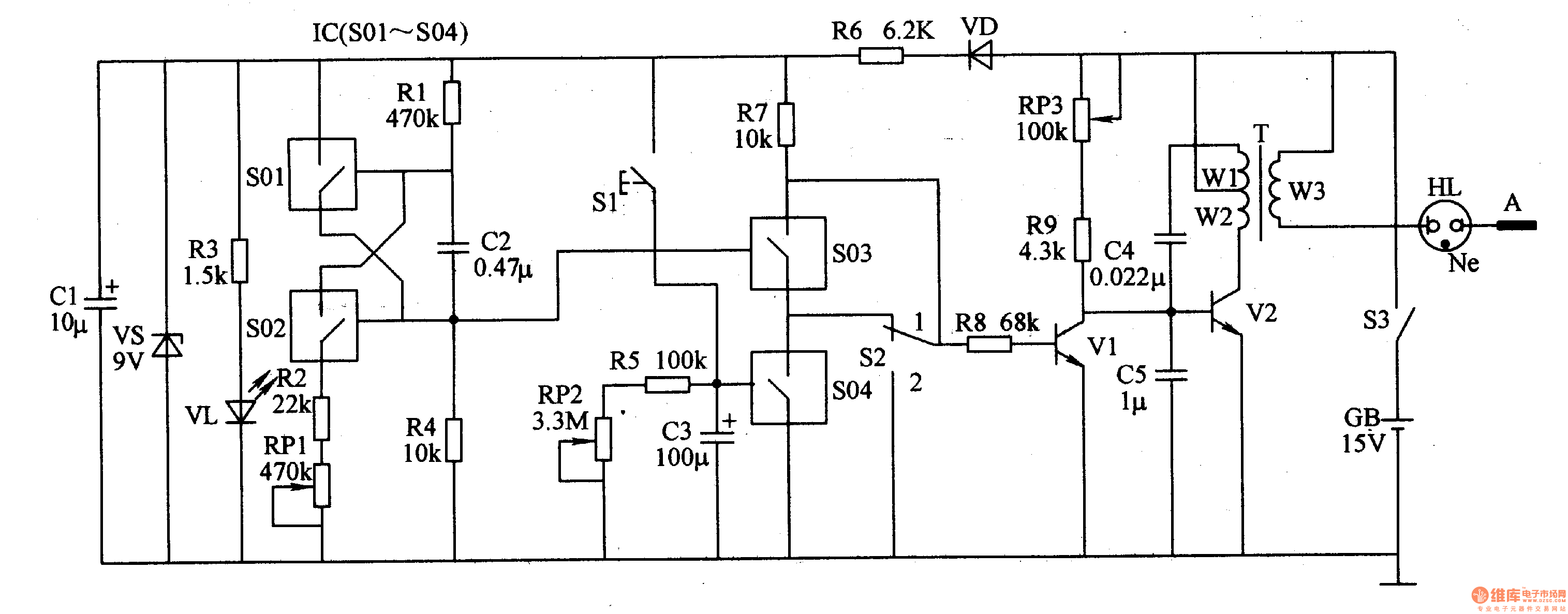
The power circuit is composed of a power switch S3, a battery GB, a diode VD, a resistor R3, a R6, a capacitor C1, a Zener diode VS, and a power indicating LED VL.
The multivibrator is composed of analog electronic switches S01 and S02 and resistors R1, R2, R4, potentiometer RP1, and capacitor C2 inside the electronic switch integrated circuit IC (S1-S04).
The timer circuit is composed of a control button S1, a resistor R5, a potentiometer RP2, a capacitor C3, and an analog electronic switch S04 inside the IC.
The control circuit is composed of a control switch S2, resistors R7, R8, an analog electronic switch S03 inside the IC, and a transistor vl.
The ultrasonic oscillator is composed of a potentiometer RP3, a resistor R9, capacitors C4, C5, a step-up transformer T, and a transistor V2.
The output circuit consists of winding W3 of T, æ°– indicator HL and electrode A.
Turn on the power switch S3, GB l5V DC voltage is directly supplied to the ultrasonic oscillator; the other path is regulated by VD and R6 current limiting, Cl filtering, VS voltage regulation becomes 9V DC voltage, as the working power of the IC, After R3 is limited, VLA will be illuminated.
After the ultrasonic oscillator oscillates, a high-frequency pulse high voltage of 48 kHz and 6-8 kV is generated in the winding W3 of the T, and the high voltage of the pulse is discharged to the human body by HL (electrode A is connected to the lesion portion of the human body) to serve as an auxiliary treatment. .
When S2 is placed in the "1" position, the ultrasonic oscillator is controlled by the timer. Press S1, C3 fast charging, the analog electronic switch S04 inside the IC is turned on, so that VI is cut off (after releasing Sl, C3 is slowly discharged through R5 and RP2), then the ultrasonic oscillator continues to oscillate and the output is continuous. Ultrasound.
When the timing time is over (C3 discharge is completed), the ultrasonic oscillator is modulated by the 100 Hz low frequency signal output from the multivibrator to output intermittent ultrasonic waves.
Adjusting the resistance of RPl can change the oscillation frequency of the multivibrator.
Adjust the resistance of RP2 to change the timer's timing.
Adjusting the resistance of RP3 can change the oscillation frequency of the ultrasonic oscillator.
Component selection
Rl-R5 and R7-R9 select 1/4W metal membrane resistor for use; R6 selects 1/2W metal membrane resistor for use.
The RPl-RP3 uses a small organic solid potentiometer or a variable resistor.
Both Cl and C3 use aluminum electrolytic capacitors with a withstand voltage of 25V; C2, C4 and C5 use monolithic capacitors or polyester capacitors.
VD selects 1N4007 silicon rectifier diode for use.
VL selects φ3mm LED.
VS selects 1W, 9V Zener diode.
Vl selects S9013 type silicon NPN transistor for use; V2 selects 2N5551 type silicon NPN transistor for use.
IC selects CD4066 or MCl4066 type electronic switch integrated circuit.
T uses a line output transformer of a black and white TV set or a pulse transformer of a high voltage electric shock.
S1 selects the move button; S2 selects the single-pole two-position switch; S3 selects the single-pole power switch.
GB uses a l5V laminated battery.
HL selects the common æ°– indicator.
power connector is used in power module system. It can select the matching power + signal connector according to the need. The feature is that the number of power and signal contacts and the matching sequence can be selected arbitrarily while keeping the connector size and contact core number unchanged.
Plug (male) / socket (female) can be installed at 90 or 180 degrees. It supports mixed or independent combination of signal and power. The quantity range of power and signal is (2-16) pin and (12-128) pin respectively
Product features
High temperature resistant, glass fiber reinforced and flame retardant polyester is used as insulation material
Copper gold composite conductor with high conductivity is used, and the contact area of the conductor is plated with gold
It adopts shrapnel contact, which has the characteristics of integration, small volume, large current carrying capacity, soft plug-in, blind plug-in, self guidance and high dynamic contact reliability. This series of products can be interchanged with FCI's powerblade series and Tyco's multi-beam series
There are three sizes of center distance of power contact: 5.08mm, 6.35mm and 7.62mm
The length of power hole / signal pin can be selected in two sizes. The power rated current is 45A and the signal rated current is 2.5A
Power+ Signal Power Connector
ShenZhen Antenk Electronics Co,Ltd , https://www.antenkwire.com