What is Joule Thief? The Joule Thief circuit is a simple self-oscillating boost circuit that is small, low cost, and easy to make. It is usually used to drive lighting loads. It can use up almost all of the energy in a single cell, even if the voltage level is already well below the battery that is considered "fully discharged" ("dead") in other circuits.
Please note the description of "boost". This means that the increase in output voltage comes at the cost of higher input current losses. Traditional science says that Joule Thief circuit can never reach COP>1. The conventional Joule Thief circuit is shown in the figure below. It always has an energy loss between the collector and emitter of the transistor.
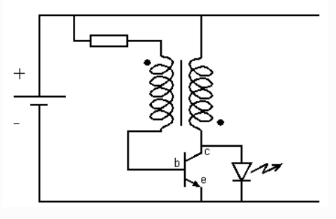
Appropriately modify this circuit can get energy from the environment to the output. It is quite simple to achieve this. First of all, before we start talking about the circuit, I want to tell you something strange about LEDs:

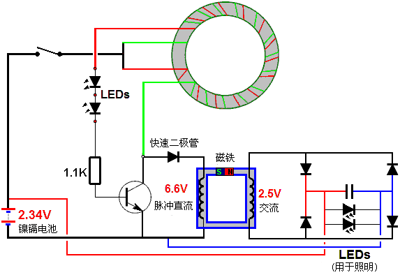
Note that you can light up a light-emitting diode with only 1.5 volts and a brighter light with 3 volts. However, if two light emitting diodes are connected in series, then the voltage of 3 volts will be too low, so it will not light up at all and the current will be zero. Well, strangely, a 1.5V can light up an LED. However, 3V cannot allow two LEDs in series to emit light. Also, although the resistance controls the brightness of the light, it does not change the desired voltage in any way. Now, it's time to point. I applied this to the Joule thief, and when I did this, I got a COP>1 and the circuit was as follows:
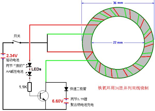
The input current for this circuit is 12.5 milliamps 12.5 milliamperes (30 milliwatts), while the output current is 6.60 volts 8 milliamperes (52.8 milliwatts), which is COP = 1.8, or the input power is 80% greater than the output power . The ferrite ring is wound with a 0.4 mm diameter enamelled copper wire (American Wire Gauge No. 26), and the turns are tilted in the diagram. The actual direction of the turns is radial, and the direction of the turns is not Affect the circuit performance. It is estimated that the diameter of the ferrite ring is not critical, but this diameter is only measured. The fast diodes can be FP607, UF5408 or the like. The base and emitter of the triode can also be connected instead of the high speed diode. The LED used is 8 mm in diameter. It is important to find the input voltage in this circuit. The optimal input voltage is between 2.2 volts and 2.5 volts, so two nickel-cadmium or two nickel-metal hydride batteries are probably the best input, because higher voltages only lead to larger input currents, while at the output power There is no optimization on it. The key to obtaining free energy for this circuit is to use at least two light emitting diodes connected in series. They are placed at the base of the transistor, and the current flows to the base, and the current fluctuations caused by its "strange things" will increase the energy from the output. One important point is that there must be at least two LEDs, and the circuit must not be self-starting because if you do so, the input voltage is too high and the circuit operation will be COP <1. Therefore, you need to start the circuit by hand, and another very important point is that the output voltage should be at least twice the input voltage.
The characteristics of this technology:
• COP> 1 can be implemented and the circuit can be modified appropriately to become self-powered. • You can extract the energy of a "exhausted" battery and supplement it with energy from the environment. • Why should you go and let the circuit charge itself at home? • Interestingly, this circuit emits high-frequency sounds that can often repel mosquitoes!
Fine-tuning the circuit: There are 5 parameters involved in the operation of the circuit:
1. Input Voltage, 2. Output Voltage, Coil Winding, 3. Ring Diameter, 4. Number of LEDs, and 5. Resistance to Transmit Current to Transistor Base.
The first step in assembling the circuit is to check the LEDs you want to use. These LEDs are to be connected in series, so start from two and connect across the battery. If the LED is on, add an LED until the LED chain crosses the battery. Doing so will increase the circuit's performance factor COP by one, and the output power will exceed the input power. When installing a ring, remember that the more windings around the ring, the greater the impedance of the coil, which will increase the COP value, but too many turns will lead to a smaller current, which in turn means that the charging of the output is reduced rate. The output voltage should always be more than twice the input voltage (example: 2.35V input, 6.60V output).
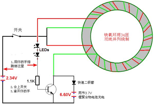
When the circuit is built as above, if the switch is turned on, the input voltage will be too high, so keep adding an LED until the circuit is no longer self-starting. Then, start running it with your finger, and by simply bypassing the LED chain with your body resistance, it is very easy to get the circuit to oscillate. This is the low voltage part of the circuit, so there is absolutely no risk of electric shock. Another method is to replace your finger with a resistor and use a push button switch to trigger the circuit. A further improvement is to add more LEDs until you reach a point where the circuit won't start, even if you try to make it run with your finger. When this point is reached, remove one LED and run the circuit. Compare the input and output power levels, then remove one LED and repeat those power measurements. Keep doing this while you still have more than two LEDs, until you determine the most effective number of LEDs in your circuit. This is the best COP performance you can find for your circuit. The LEDs in this circuit are used to cause the base current to fluctuate as a mechanism to get COP > 1 performance, so they are not there for lighting. You can increase the resistance value, thereby reducing the amount of input current used, but as a result, the output power is reduced. In my circuit, I used a 1100 ohm resistor.
Further experiments:
This part is about I have done some experiments to see if I can improve the performance of Joule Thief. Obviously, I haven't tried every possible configuration yet, so I invite you (the readers) to do further experiments because the Joule thief is obviously a good circuit for experimentation. For a 1000 mAh 7.4 volt lithium battery pack, the charging rate of only 8 mAh is too low, so it is necessary to increase the charging rate. This can be done by paralleling two or more of these circuits as follows:
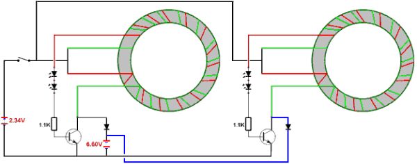
The battery is almost completely discharged and has a higher internal resistance than the new battery. Therefore, the higher the current drawn through the circuit, the lower the efficiency of the circuit. As a result, the effective input voltage used by this circuit is actually lower than the 2.34 volts shown in the schematic.
So maybe it should be configured as follows:
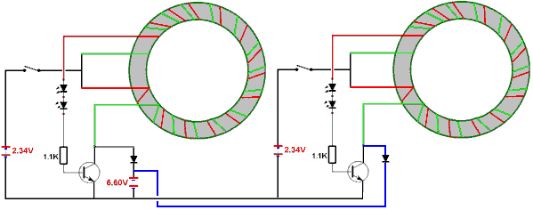
Remember that the output voltage should always be twice the input voltage. So if you want to charge a lower voltage nickel-cadmium battery, use a step-down transformer as follows:
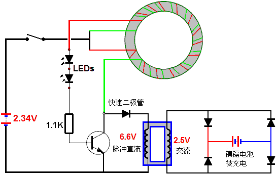
With appropriate modifications, it can become self-powered and self-charging as follows:
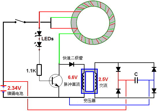
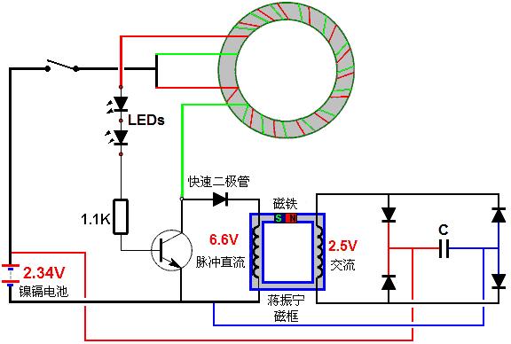
The performance of this circuit can be further enhanced with asymmetrical transformers, such as the Jiang Zhenning box or the Sienna Heinz transformer, as follows:
Always-on circuit: The higher the voltage, the lower the impedance of the LED. Therefore, the performance of the circuit is reduced by negative feedback. Therefore, the circuit can be stabilized as follows:
Jiang Zhenning Magnetic Frame
Lawrence Tseung's magnetic frame
Jiang Zhenning recently applied a very similar principle to a subtle design. He used a similar magnetic frame and embedded a permanent magnet into one of the frame arms. Then a sharp DC pulse is applied to the coil wound on one side of the frame, and electric energy is taken out from the coil wound on the other side of the frame.
He showed the device three different modes of operation, as follows:

Jiang Zhenning commented on three possible configurations. The first of these is a standard commercial transformer configuration, a frame made of an insulated iron shim to reduce the “vortex†current, and also in the frame and the useful, linked coils on both sides of the frame. The magnetic pulse in the circle around the box at right angles. As we all know, the output power of this configuration is never greater than the input power.
However, this arrangement can be varied in several different ways. Jiang Zhenning chose to remove part of the box and replace it with a permanent magnet, as shown below. This can greatly change the condition of the magnetic flux that is caused by the permanent magnets to continue to circulate around the frame before any alternating voltage is applied to the input coil. If the pulse input power is applied in the wrong direction, as shown in the figure, the magnetic flux generated by the pulse input is opposite to the magnetic flux that has flowed from the permanent magnet in the frame, then the output is actually lower than if there were no permanent magnet originally. .

However, if the pulse input coil causes the current in the coil to generate a magnetic field to enhance the magnetic field of the permanent magnet, then it is possible to make the output power greater than the input power. The "performance factor" or "COP" of the device is the output power value divided by the input power value that the user must input to operate the device. In this example, the COP value can be greater than one:

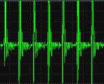
Because it disturbs the purists, it should be mentioned that although the square wave input signal is applied to the input of each of the above illustrations, the output will not be a square wave, although this display is only for clarity. In contrast, when the pulse frequency exactly matches the resonance frequency of the output winding, the input and output coils convert the square wave to a low-mass sine wave to become a pure sine wave. The oscilloscope here shows a typical output power waveform with such pulses approaching 390,000 times per second.
Any particular frame is limited by the materials used to make it and therefore also limits the amount of magnetic flux. Iron is the most commonly used material for making such frames, and it has a very well-defined saturation point. If the permanent magnet is so powerful that it causes the frame material to saturate before the input pulse is applied, then the positive DC pulse will have no effect, as shown. This is just common sense, but it clearly shows that based on the size of the frame, the choice of magnets should not be too strong and why it should be.
Here is an example. A person copied the design of Mr. Jiang Zhenning and found that he did not receive any energy at all. He consulted Mr. Jiang. Chiang asked him to take out the magnet and try it. He did so, and immediately obtained the standard output, showing that his input configuration and output measurement system worked perfectly. So he understood that the three magnet stacks he used in the frame were too strong. So he reduced the stack and used only two magnets, so he immediately obtained a COP performance of 1.5 (power output 50% larger than input).
LaserSaber Joule Thief Lighting Circuit
Another very successful variant based on Joule Thief entered the public domain on October 4, 2012, details on his website. His reforms are extremely simple in concept and structure:
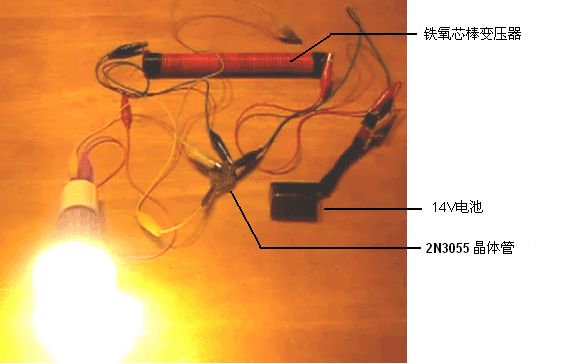
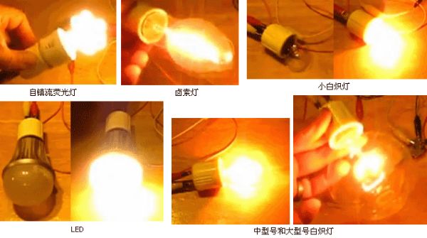
In his video: http://solarpower.energygratis.com/2012/10/09/solar-electricity-super-joule-ringer-3-0-real-world-power-made-easy/ He demonstrated It uses it to light a mains voltage LED bulb (see above), a mains incandescent lamp, a halogen lamp and a compact fluorescent lamp that also carries a ballast, which is the lamp without any modification sold in the store. . This circuit is:

The unusual feature of this "Super Joule Loop 3.0" circuit is the feedback from the load (bulb) to the base of the 2N3055 transistor. The circuit is a high-frequency DC inverter. It can't be simpler. It should be noted that the high-frequency output voltage spike is not a sine wave nor a voltage control, so this is not a circuit that drives something like a TV. The high-frequency oscillations of the transistor are governed by the specifications of the 72 turns of the primary winding of the transformer. The output voltage level is a combination of the battery voltage and the transformer turns ratio. To increase the output voltage, increase the number of secondary turns. The number of turns is not specified, except that the wire turns along the entire length of an 8-inch (200-mm) long ferrite core bar, using 0.32 mm diameter enameled copper wire (28-gauge wire gauge or 30-gauge standard wire) Regulations are closely side-by-side. Using calculations, it is shown that there are approximately 600 turns around the ferrite bars. The ferrite magnet itself has a diameter of 0.625 inches (15.88mm) and seems to be not easy to find. However, I strongly suspect that the diameter of a ferrite rod is really important. The two coils are wound in the same direction in the ferrite rods, first wound around the secondary, placed under the primary, and the primary is wound with insulated wires of 1.63 mm diameter (No. 14 American wire gauge or No. 16 standard wire gauge). Hey. No current is marked, but it appears to be quite high, where there are exactly two spiral coil drive sections. 110 volt lightbulb demo in his video:
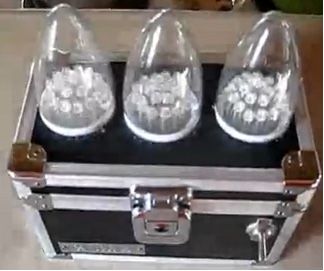
The second very useful lighting system of "LaserSaber" is a Joule thief-driven LED lighting box that can be operated with only one AA rechargeable battery. It looks like this:
At the end of the box is a monolithic small solar panel:
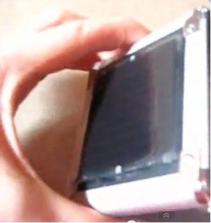
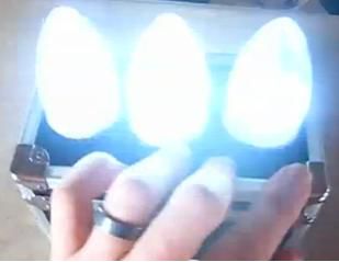
It can charge the battery during the day. This device is built into a small box that can be opened for easy wiring and LED lights are configured at different angles. What you don't see in these pictures is that the other big LED's cluster lights were also lit. Slightly regrettable is that it allows the LED light to shine on the solar panel, because it can charge some batteries when the light is on. LED can provide a lot of light:
The material of this product is PC+ABS. All condition of our product is 100% brand new. OEM and ODM are avaliable of our products for your need. We also can produce the goods according to your specific requirement.
Our products built with input/output overvoltage protection, input/output overcurrent protection, over temperature protection, over power protection and short circuit protection. You can send more details of this product, so that we can offer best service to you!
Lcd Adapter,Mini Size Lcd Adapter,Security Lcd Adapter,Waterproof Lcd Adapter
Shenzhen Waweis Technology Co., Ltd. , https://www.waweisasdapter.com