The inverter converts DC power (battery, battery) into alternating current (typically 220V, 50Hz sine wave). It consists of an inverter bridge, control logic and filter circuits.
Simply put, an inverter is an electronic device that converts low voltage (12 or 24 volts or 48 volts) direct current to 220 volts AC. Because we usually use 220 volt AC to be converted to DC, and the inverter has the opposite effect, hence the name.
What is a sine wave inverter?The inverter can be classified according to its output waveform, and is divided into a square wave inverter, a modified wave inverter and a sine wave inverter.
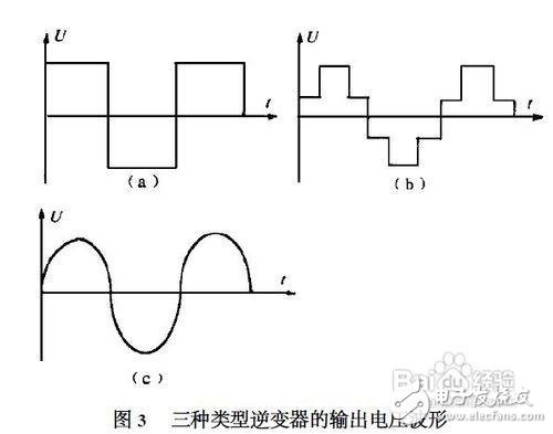
Therefore, the definition of a sine wave inverter is an inverter whose output waveform is a sine wave.
Its advantage is that the output waveform is good, the distortion is very low, and its output waveform is basically consistent with the AC waveform of the mains grid. In fact, the excellent sine wave inverter provides higher AC power than the grid. The sinusoidal inverter has low interference to radio and communication equipment and precision equipment, low noise, strong load adaptability, can meet all AC load applications, and the overall efficiency is high; its shortcoming is the line and relative correction wave inverse The transformer is complex, requires high control chip and maintenance technology, and is more expensive.
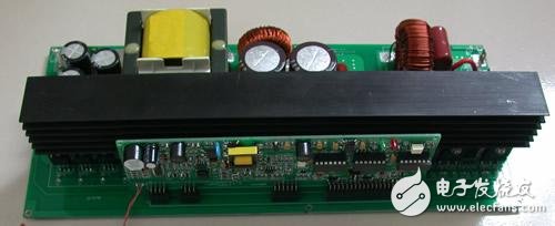
Sine wave inverter physical map
Before introducing the working principle of the sine wave inverter, first introduce the working principle of the inverter.
The inverter is a DCtoAC transformer, which is actually a process of voltage inversion with the converter. The converter converts the AC voltage of the grid into a stable 12V DC output, and the inverter converts the 12V DC voltage output from the Adapter into a high-frequency AC power. Both parts also use more pulse widths. Modulation (PWM) technology. The core part is a PWM integrated controller, the Adapter uses UC3842, and the inverter uses TL5001 chip. The TL5001 operates from a voltage range of 3.6 to 40V and features an error amplifier, a regulator, an oscillator, a PWM generator with dead-band control, a low-voltage protection loop, and a short-circuit protection loop.
Input interface part: The input part has 3 signals, 12V DC input VIN, working enable voltage ENB and Panel current control signal DIM. VIN is provided by the Adapter. The ENB voltage is provided by the MCU on the main board. The value is 0 or 3V. When ENB=0, the inverter does not work, and when ENB=3V, the inverter is in normal working condition; and the DIM voltage Provided by the main board, the range of variation is between 0 and 5V. The different DIM values ​​are fed back to the feedback end of the PWM controller. The current supplied by the inverter to the load will also be different. The smaller the DIM value, the current output by the inverter. It is bigger.
Voltage Start Circuit: When ENB is high, the output voltage is high to illuminate the backlight tube of the Panel.
PWM controller: It has the following functions: internal reference voltage, error amplifier, oscillator and PWM, overvoltage protection, undervoltage protection, short circuit protection, output transistor.
DC conversion: The MOS switch tube and the energy storage inductor form a voltage conversion circuit. The input pulse is amplified by a push-pull amplifier and then drives the MOS tube to perform a switching action, so that the DC voltage charges and discharges the inductor, so that the other end of the inductor can be exchanged. Voltage.
LC oscillation and output circuit: ensure the required voltage of 1600V to start the lamp, and reduce the voltage to 800V after the lamp is started.
Output voltage feedback: When the load is working, the sampling voltage is fed back to stabilize the voltage output of the I inverter.

Complex sine wave circuit diagram
The difference between the sine wave inverter and the ordinary inverter is that the output waveform is a complete sine wave with low distortion rate, so there is no interference to the radio and communication equipment, the noise is also low, the protection function is complete, and the whole machine has high efficiency.
The reason why the sine wave inverter can output a complete sine wave is because it uses a more advanced SPWM technology than PWM technology.
The SPWM principle is based on the equivalent principle of a pulse acting on a time-function device: if the pulse acts on a time-function device, the product of the peak and the action time is equal, and the equivalent of these pulses can be approximated.
SPWM is based on a fixed frequency fixed peak (such as switching frequency 10k) triangular wave and variable frequency transformed reference sine wave (fundamental wave) to pulse the DC voltage (duty cycle variable) to approximate the reference sine wave effect On the device. Adjusting the amplitude and frequency of the reference sine wave to produce a DC voltage pulse width modulated wave of an equivalent reference sine wave of different amplitudes and frequencies.
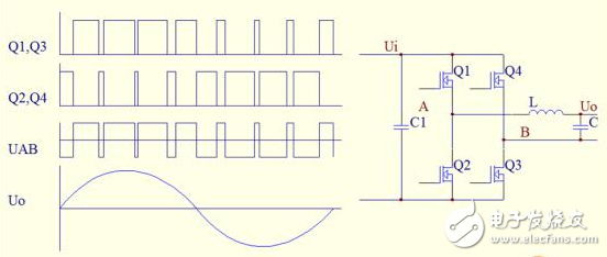
SPWM circuit diagram
Recommended reading: sine wave inverter introduction _ sine wave inverter working principle
Product categories of Cloth Pen Nib, it is belong to Passive Stylus Pen. Passive stylus pen is characterized by being cheap and without charging. But compared with the active capacitive stylus pen, its tip diameter is larger, so it cannot be used in works with high precision. Using high-quality conductive cloth head, smooth contact with the screen.
Cloth Pen Nib,Multi-Functional Pen Stylus Pen,Stylus Pencil With Clip,Touch Stylus Pencil
Shenzhen Ruidian Technology CO., Ltd , https://www.szwisonen.com