With the improvement of the level of automation in industrial production, the application of various sensors is also increasing. As a sensor for speed and displacement feedback, rotary encoder is mainly used in CNC machine tools, high-precision closed-loop speed control systems, servo motors, asynchronous motors, stepping motors, elevator traction machines, elevator door machines and even mechanical axes. Automatic control of speed and displacement information feedback to ensure high-precision and stable operation of the machine, thereby improving production efficiency and ensuring safe operation.
In this paper, based on the application of rotary encoder in industrial field, based on LPCI768 hardware platform, a rotary encoder acquisition module is designed. The module has high-precision analysis, shaping and decoding circuits, which can simultaneously input the input signals of two encoders. Analysis and decoding. The processed rotation signal is acquired and digitally filtered by a high performance processor. The rotary encoder also calculates the angular velocity of the two encoder signals. The final module sends the acquired rotational position value and angular velocity value to the DPU (Distributed Processing Unit) via the CAN bus for industrial use.
1 rotary encoder
A rotary encoder is a sensor that measures the movement of a rotating component. It is a sensor that converts the amount of mechanical displacement of a rotation into an electrical signal, and processes the signal to detect position, speed, and the like. The so-called encoding is actually the process of converting the information of the rotation angle into an electrical signal readable by the single chip microcomputer. Rotary encoders can be divided into contact type, photoelectric type and electromagnetic type according to the working principle. According to the form of output signal, it can be divided into two types: incremental type and absolute value. Among them, incremental type encoder is the most commonly used in industry. Encoder.
The incremental encoder includes a code wheel, a light emitting element, a receiving element, and a signal processing portion. When the shaft rotates, the code wheel rotates, so that the line is transparent, and the space is opaque. The transmitted light is received by the receiving component and input to the signal processing part to generate a pulse signal output. The output signal generally includes A and B. Two phases (phase difference 90°), some encoders will output a zero pulse Z every revolution, as the mechanical reference zero. When the spindle rotates in the clockwise direction, the A channel signal is located before the B channel; when the spindle rotates counterclockwise, the A channel signal is located after the B channel, so that it can be judged whether the spindle is forward or reverse.
2 CAN bus
The Controller Area Network (CAN) is one of the most widely used fieldbuses in the world. The CAN bus was originally developed for automotive applications by Bosch in Germany in 1983. It is a serial communication network that can effectively support distributed control and real-time control. It belongs to the field of Field Bus. With the continuous improvement and development of the CAN bus, it has been adopted as an international standard by international standards organizations.
The CAN bus is a multi-master serial communication bus. The basic design specification requires high bit rate and high anti-interference, and can detect any errors generated. When the signal transmission distance reaches 10 km, the data transmission rate of up to 5 kb/s can still be provided. After the CAN protocol is standardized by lSO, there are two kinds of IS011898 standard and IS011519 standard. The difference between the two is that the definition of the physical layer is different. ISOll898 is a CAN high-speed communication standard with a communication speed of 125 kb/s to -1 Mb/s, and ISOll519 is a CAN low-speed communication standard with a communication speed of 125 kb/s or less.
3 hardware design
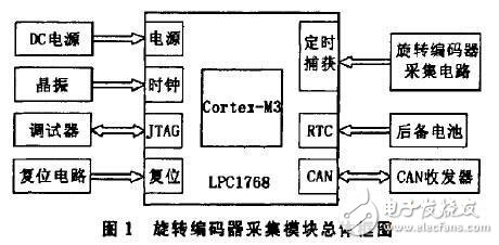
According to the system function requirements, this paper selects the LPCI768 processor produced by NXP, which is a 32-bit processor based on ARMCortex--M3 core. It has 3 pipelines and Harvard architecture with independent local command and data bus. A slightly lower performance third bus for peripherals, and an internal prefetch unit that supports random turn-up, operating at up to 100MHz. Peripheral components of the LPCI768 processor include up to 512 kB of flash memory, 64 kB of data memory, 4 general-purpose timers, 8-channel 12-bit ADC, 10-bit DAC, motor control PWM, 4 UARTs, 2 CAN channels Ultra-low power RTC with independent battery and up to 70 general purpose I/O pins. Figure 1 is a general block diagram of the rotary encoder acquisition module.
3.1 CPU part
According to the chip manual, the LPCI768 can select the internal RC oscillator or the main oscillator as the system clock source, and the internal oscillator can work in the frequency range of 1 MHz to 25 because the internal RC oscillator accuracy cannot meet the CAN bus communication requirements. MHz, so a 12 MHz crystal plus a 22 pF capacitor is used to form the Pierce oscillator as the clock source for the main oscillator. Since the system does not use the A/D module of the chip, VDDA can be connected to 3.3V with VDD. A 0.1uF decoupling capacitor should be connected between each pair of VDD and GND pins. At the same time, the JTAG and communication pins are connected to VDD through a 10k pull-up resistor to improve signal transmission stability.
3.2 Rotary encoder acquisition part
When the rotary encoder is used for angular positioning or measurement, the oscillation of the rotating shaft may cause the jitter of the output waveform of the encoder, which may cause miscounting. In this case, the waveform cannot be correctly counted. The system passes a single stable State triggers to eliminate jitter in the output pulse signal of the rotary encoder. Figure 2 shows one of the circuits in the rotary encoder acquisition circuit.

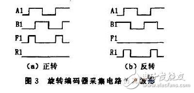
The analysis circuit shows that when the rotary encoder rotates forward, F1 outputs a pulse sequence. When the rotary encoder is inverted, the R1 output pulse sequence is closed, and the circuit simulation waveform is shown in Fig. 3.
3.3 CAN bus communication part
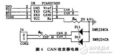
The LPC1768 processor supports the CAN 2.0B specification and is compatible with the IS011898-1 standard. Based on this, this paper selects the PCA82C250 chip produced by Philips Semiconductors as the CAN bus transceiver, the communication matching resistor selects 120, i1, and the CAN transceiver circuit is shown in Figure 4.
3.4 Power section
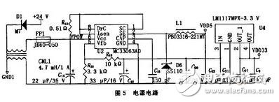
The operating voltage of the LPC1768 is 3.3 V, and the voltage of the CAN transceiver and the rotary encoder is 5 V. Therefore, the MC33063 is used to reduce the input voltage to 5 V for use by the relevant circuit, and then pass the LM1117-3.3V. The 5V voltage drops to 3.3V as the operating voltage of the processor. The power supply circuit is shown in Figure 5.
4 software design
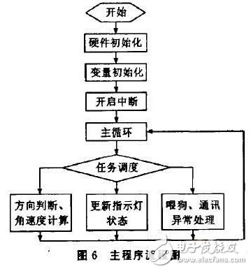
The system adopts RealView MDK-ARM V4.10 as the development platform, and C language as the main development language. The program is mainly divided into three parts: the rotary encoder acquisition part adopts the interrupt mode, and the input pulse signal is completed by the LPC1768 timing capture unit. The counting operation; the CAN communication part also uses the interrupt mode to listen to commands from the DPU or other control host, and then performs the corresponding data transfer task; and the main program completes the rotation direction of the rotary encoder through a certain time scheduling algorithm. The calculation of the angular velocity and the setting of the corresponding indicator status, handling of abnormal conditions during CAN communication, feeding the dog, etc. The main program flow chart is shown in Figure 6.
5 Conclusion
The rotary encoder acquisition module designed in this paper is suitable for various industrial control sites and has a wide application prospect. It has been initially verified by the laboratory and applied to an industrial field test. The module meets the user requirements for the signal processing results of the rotary encoder, and can reliably communicate with the field control system. The performance is stable and has strong anti-interference. Ability and high security.
Carbon Fiber Rigid Felt Board,Heat Insulation Hard Felt Ring,Conical Carbon Fiber Hard Felt Ring,Carbon Fiber Heat Insulation Hard Felt
HuNan MTR New Material Technology Co.,Ltd , https://www.hnmtr.com