Use wireless transceiver modules, voice modules, digital encoding / decoding dual-function integrated circuits and high-brightness LED digital tubes to design wireless call systems. When the production frontline personnel need to call for help in an emergency, they can start the wireless call system. After receiving the call signal, the receiver amplifies and processes through a series of circuits of the receiving device, outputs a control signal, drives the digital display to work, displays the call area, and at the same time reminds the person on duty with a voice alarm. The system adopts a modular circuit design, which has the characteristics of anti-vibration, debugging-free, digital display, voice prompt, and reliable operation. The working distance is 1000m. It can be used in mining engineering, power control equipment, security systems, industrial data collection and other fields.
0 Preface
The core component of the wireless transmission system is the wireless transceiver module, which includes the transmitter module and the receiver module. Transmitting module TX3310 uses the most advanced surface acoustic filter to stabilize the frequency, the frequency stability reaches the order of 10-5, the working frequency is 315MHz, its small size, the working stability reaches the industrial level, and can be used to transmit low frequency digital codes signal. The receiving module RX3310 contains a set of superheterodyne crystal oscillator receiving and data processing circuits. It has the characteristics of stable frequency and good anti-interference. It is used to receive the wireless remote control signal sent by the transmitting module. The system uses the digital coding / decoding dual-function integrated circuit UM3758-108A, which ensures the reliability of the work.
1 Module structure
1.1 TX803 wireless voice transceiver module
TX803 is a voice transmission and receiving module newly developed and produced by Shanghai Fumeisi Electronic Technology Co., Ltd., which can realize the wireless transmission of voice. This module is divided into two modules: transmitting and receiving. The FM modulation circuit adopts crystal frequency stabilization. The frequency is 79.000MHz and other external frequency points of the FM broadcast section. The frequency is stable and the voice is clear. The working voltage of the transmitting module is 3 ~ 9V, the limit value is 10V, the working current is 20mA, and the working distance is 500 ~ 1000m.
1.2 TX3310 / RX3310 wireless data transmission / reception module
The TX3310 / RX3310 wireless data transmission / reception module circuit uses surface acoustic resonator SAW frequency-stabilized, miniature electronic components, and is made by surface-mount technology. Its small size and working stability have reached industrial level.
2 Circuit structure and working principle
The wireless call system is composed of components such as voice wireless transmission / reception module, data wireless transmission / reception module, digital coding / decoding dual-function integrated circuit.
Figure 1 shows the transmission circuit of the wireless call system. IC1 (UM758-108A) is a digital encoding / decoding dual-function integrated circuit with an operating voltage of 3 ~ 12V, a 10-bit (A1 ~ A10) tri-state coding address, and 8-bit (D1 ~ D8) Latch-type parallel data input / output terminal, which can easily realize multi-address and multi-channel digital information transmission or control, and can be used with wired carrier, wireless, infrared and other carriers to achieve long-distance transmission and control [ 3 ~ 7]. Addresses A1 ~ A10 can be wired in three states: low level 0, high level 1 or open circuit. A total of 310 = 59049 non-repetitive codes. Data D1 ~ D8 terminals can be wired in two states of low level 0 or high level 1 and used as two sets of 4-digit BCD codes. When S1 is not pressed, IC3 (TX3310) pin 1 (DATA) has no data input and is static. The delay circuit composed of IC2 (NE555) has no low-level trigger signal input due to pin 2 (TR) While in steady state, pin 3 (OUT) of IC2 outputs a low level, transistor Q1 (9013) is turned off, and IC4 (TX803) does not work. When the staff needs help to press S1, IC3 transmits the call signal according to the programmed address and data code. Because pin 2 of IC2 is triggered by low level, pin 3 is flipped from low level to high power. Ping, Q1 saturation conduction, IC4 energized work, at this time staff only need to speak into the microphone, you can send the voice signal to the duty room.
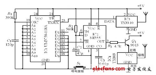
Figure 1 Transmitting circuit of wireless call system
As shown in Figure 2 for the wireless call system receiving circuit. It is mainly composed of data wireless receiving module IC5 (RX3310), voice wireless receiving module IC10 (TX803), digital encoding / decoding dual-function integrated circuit IC6 (UM3758-108A), delay circuit IC9 (NE555), LED digital tube driving circuit and Display circuit and other components.
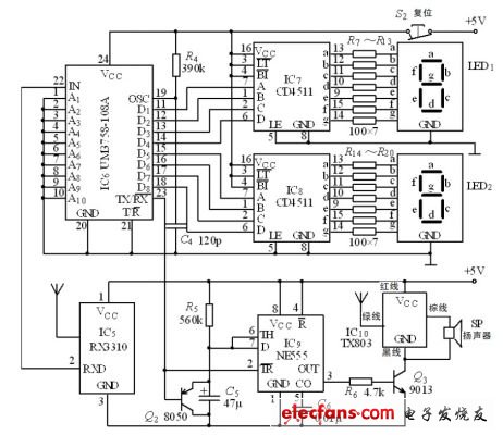
Figure 2 Wireless call system receiving circuit
The encoded data signal is received by the receiving antenna, processed by IC5 (RX3310) and IC6 (UM3758-108A) circuits, and its output controls the digital display circuit and voice delay circuit. IC7 (CD4511) and IC8 (CD4511) are dedicated translations for LED digital tubes Code chip, when the input signal is BCD code, the common cathode LED nixie tube respectively displays its corresponding decimal 0 ~ 9 font [8 ~ 9].
While the digital tube displays the call extension number, pin 3 (OUT) of IC9 (NE555) outputs a high level, the transistor Q3 (9013) is saturated and turned on, the wireless voice receiving module IC10 (TX803) is powered on, and the speaker sends out the staff Voice call information, so that the duty personnel can understand the scene of the emergency call in time.
The working power of the system is 5V, and the rechargeable battery is used as a backup power supply, which is automatically charged and converted to ensure that the system can still work normally when the AC power is cut off.
3 Conclusion
Because the system adopts radio receiving and transmitting technology and digital coding technology, a receiving host can set up several call extensions and can monitor multiple working places at the same time. This system not only has strong anti-interference ability, but also has a long and long transmission distance, which is very suitable for mining engineering, power control equipment, security system, industrial data collection and other fields.
Huawei Touch Screen Price,Mobile Phone Touch Panel,Mobile Phone LCD,Mobile Touch Screen Manufacturers
Dongguan Jili Electronic Technology Co., Ltd. , https://www.ocasheet.com