First, the integrated circuit and its characteristics
Integrated circuits use integrated processes such as oxidation, photolithography, diffusion, epitaxy, and aluminum evaporation to form transistors, resistors, wires, etc. on a small piece of semiconductor (silicon) substrate to form a complete circuit. According to the function, it can be divided into two major categories: analog integrated circuit and digital integrated circuit. Among them, integrated circuit operational amplifier (linear integrated circuit, hereinafter referred to as integrated operational amplifier) ​​is the most widely used analog integrated circuit, which is essentially a high gain. Directly coupled to a multi-stage amplifier circuit.
Integrated circuit features
1. The accuracy of a single component is not high, and it is also affected by temperature, but the performance parameters of components are relatively consistent and the symmetry is good. Suitable for forming a differential circuit.
2. A resistor having a resistance that is too high or too low is not easy to manufacture, and the tube is used much more in the integrated circuit and the resistor is used less.
3. Large capacitors and inductors are not easy to manufacture, and multi-stage amplifier circuits are directly coupled.
4. In the integrated circuit, in order not to make the process complicated, a single type of tube is used as much as possible, and the types of components are also small. Therefore, the integrated circuit has a large difference and characteristics in comparison with the discrete component circuit. A constant current source and a current source composed of a common diode and a triode replace the large collector resistance and provide a small bias current, and the diode is replaced by the emitter junction of the triode.
5. In the integrated circuit, the NPN tube is made into a longitudinal tube, and the β is large; the PNP tube is made into a lateral tube, and the β is small and the PN junction has a high withstand voltage. NPN tubes and PNP tubes cannot be paired. For PNP tubes, β and (β+1) are quite different, and IB is often not negligible.
Second, the composition of the integrated operational amplifier circuit and the role of each part
1. composition
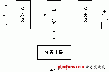
2. effect
As shown in the figure, the integrated transport and discharge route is composed of four parts. The input stage is a high-end differential amplifier with double-ended input. It requires high Ri, Aod, KCMR, and small quiescent current. Most of the performance parameters of the integrated op amp are affected, so the update changes the most. The role of the intermediate stage is to make the integrated operational amplifier have a strong amplification capability, so the composite tube is often used as the amplification tube, and the current source is used as the collector load. The output stage is required to have a wide linear range, small output resistance, and low nonlinear distortion. The bias circuit is used to set the static working point of the amplifier circuit of the integrated operational amplifier
Third, the integrated voltage transmission characteristics of the operational amplifier
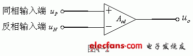
Symbol
The non-inverting input terminal indicates that the input voltage is the same as the output voltage phase. If uP "0", then uO "0"; uP "0, then uO" 0.
The inverting input terminal indicates that the input voltage is opposite to the output voltage phase. If uN "0", then uO "0; otherwise uN "0, then uO" 0.
2. Voltage transmission characteristics
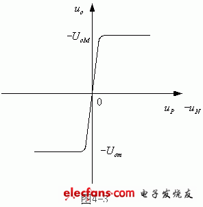
The so-called voltage transfer characteristic is actually a relationship curve as shown in Figure 4-3, which is the relationship between the output voltage uo and the input voltage ui. The relationship curve is clearly two regions, a linear amplification region and a saturation region, and the oblique line reflects the relationship between the input and output of the linear amplification region. The slope is the voltage amplification factor Av=uo/ui, the ratio of the output to the input amplitude (or rms), and the horizontal line at both ends is the saturation region, indicating that the output voltage uo does not change with the input ui = uP - uN, but is constant The value +Uom (or -Uom), the characteristic curve also shows that the linear region is very narrow, because the differential mode open-loop magnification Aod is very high, up to several hundred thousand times, only when ui =|uP - uN | At 28μV, the circuit operates in the linear region.
Pd 45W,45 W Usb C Charger,45 Watt Usb C Charger,Pd 45W Fast Charger
ShenZhen Yinghuiyuan Electronics Co.,Ltd , https://www.yhypoweradapter.com