I. Overview
In industrial conveying equipment, it is necessary to realize the linkage of multiple motors according to a certain speed ratio. In the past, this function was mostly achieved by mechanical devices. Electrical solutions often rely on a large number of PLC analog modules to make the system have low flexibility, large maintenance workload, complicated process, high cost, and difficult installation. And other disadvantages. By adopting Danfoss VLT5000 series inverters, we have new solutions.
2. System composition and principle
The system consists of 5 VLT5000 series inverters and auxiliary switches, indicator lights, potentiometers, and necessary electrical components such as air switches. The speed of inverter A in Figure -1 is given as the main speed (its own speed is given by an external potentiometer). Terminal 42 of inverter A corresponds to its own output speed, which is automatically converted into a pulse signal (frequency) and output B frequency converter, as the speed reference signal of B frequency converter (pulse signal is received through terminal 29 of B frequency converter), and then the internal frequency of 327 is modified by B frequency converter, and after calculation, the corresponding output certain speed . Similarly, the B inverter corresponding to its own output speed is automatically converted into a pulse signal (frequency) through the No. 42 terminal to output the pulse signal (frequency) as the speed reference signal of the C inverter (through the C inverter's terminal 29 to receive the pulse signal ), And so on, up to E frequency converter. In this process, all the speed reference signals are digital (that is, the speed signal changes the given pulse frequency and combines with its own internal calculation to achieve different speeds).
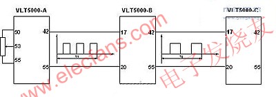
figure 1
As shown in Figure-2, the system is compatible with functions such as speed reference, manual automatic switching, speed fine-tuning, and fault alarm. The specific implementation also uses the advanced parameter menu switching function of DANFOSS inverter. Terminal 27 of VLT5000 in the figure This function is specifically executed. After the 27th terminal of all inverters is opened or closed in actual application, the speed reference of each inverter is automatically converted into a single potentiometer signal, and the pulse linkage signal described above is automatically released; In addition, terminals 19 and 29 can play a fine-tuning role in the production of the entire system. For example, when a certain section of paper is too loose or too tight in the papermaking process, the system will accelerate or decelerate instantly, so that the system can keep up with the actual changes After the error is eliminated, the system returns to the main given state; all fault lights are controlled by the small internal control relay of the frequency converter, and they will be realized automatically in the manual state or the automatic state.
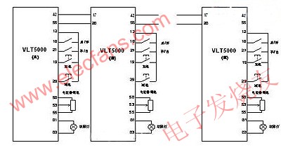
figure 2
Third, the realized function
1. The speed of 5 or more inverters runs synchronously according to the required proportion;
2. The changeover switch connected to terminal 27 controls the separate manual state and synchronous linkage state: when manual alone, the speed is given by the potentiometer; when in the linkage state, the speed is synchronized with the previous inverter in proportion;
3. The buttons connected to terminals 19 and 29 realize the speed fine-tuning function during linkage: when the button is pressed, the speed of the inverter changes accordingly, and the speed of all the inverters in the subsequent stage of the speed chain changes in proportion; after the button is released, the inverter speed Restore the original speed, the speed of all the inverters in the subsequent stage of the speed chain is restored in the same proportion;
4. The alarm of a single inverter is promptly indicated, and the maintenance is intuitive and convenient;
4. Example: Calculation of Pulse Signal
Calculation formula of host output pulse:
Y1 = K1 * F1 / X1
F1——Main speed frequency (inverter A)
X1——Par202 (Inverter A)
K1——Par342 (Inverter A)
Y1-output pulse
Calculation formula of output frequency of slave: F2 = Y1 * X2 / K2
F2——Slave frequency (inverter B)
X2——Par202 (Inverter B)
K2——Par327 (Inverter B)
Example: The speeds of the five inverters are 50Hz, 40Hz, 30Hz, 20Hz, and 40Hz respectively. Find the value of the PAR327 of the inverter at the next stage of the speed chain.
According to the above calculation formula and the value set in the synchronous linkage parameter SETUP1, find Par327 of inverter B = 6250; Par327 of inverter C = 6666; Par327 of inverter D = 7500; Par327 of inverter E = 2500.
V. Summary
Shanghai Fanfan New Building Materials Co., Ltd., Shanghai Danone Glass Wool Co., Ltd., and Nanjing Fiberglass Institute have all adopted this application. The results of the application are well reflected, meeting the customer's synchronization requirements, and the speed is stable.
Welcome to reprint, this article comes from the electronic enthusiast network (http: //)Small computer system interface (SCSI) is an independent processor standard for system level interfaces between computers and intelligent devices (hard disks, floppy drives, optical drives, printers, scanners, etc.). SCSI is an intelligent universal interface standard.
The maximum synchronous transmission rate of the original SCSI standard was 5MB / S (scsi-1, also known as narrowscsi, in 1986, the maximum support for seven devices, the clock frequency was 5MHz), and the later SCSI II specified two options for increasing the speed. One is to increase the frequency of data transmission, namely fast SCSI (in 1994, the maximum support for 7 devices) is 10 Mb / S (10 MHz) because the frequency is doubled; the other is to double the transmission frequency and increase the width of the data path from 8 bits to 16 bits. The maximum synchronous transmission speed of widescsi is 20MB / S (the clock frequency is 10MHz, in 1996, the maximum support for 15 devices).
The third generation of SCSI appeared around 1995, but there was no unified standard
1. Ultra SCSI with maximum synchronous transmission speed of 20MB / S (also known as FAST-20 SCSI, clock frequency of 20MHz);
2. Ultra wide SCSI with maximum synchronous transmission speed of 40MB / S (same as 1);
3. Ultra2 SCSI with maximum synchronous transmission speed of 40MB / S (also known as fast-40 SCSI, clock frequency of 40MHz, 1997).
Later, some newer SCSI standards appeared
1. Ultra2 widescsi with maxmum synchronous transmission speed of 80mb / S (clock frequency of 40MHz);
2. Ultra 3 SCSI with maximum synchronous transmission speed of 160MB / S (also known as ultra-160 or fast-80 wide SCSI, clock frequency of 40MHz plus double data rate, 1999);
3. Ultra 320 SCSI with maximum synchronous transmission speed of 320mb / S (also known as ultra 4 SCSI, clock frequency of 80MHz plus double data rate, 2002); 4. Ultra 640 SCSI with maximum synchronous transmission speed of 640MB / S (clock frequency of 160MHz plus double data rate, 2003, is the latest SCSI standard)
This interface is a convenient interface standard for system integration, cost reduction and efficiency improvement. More and more devices will use the SCSI interface standard. Therefore, there are many hard disks and SCSI CD-ROM drives with SCSI interface. However, due to the cost problem, they are mainly used on medium and high-end servers and workstations.
Metal Male SCSI Cover Section
ShenZhen Antenk Electronics Co,Ltd , https://www.antenkcon.com