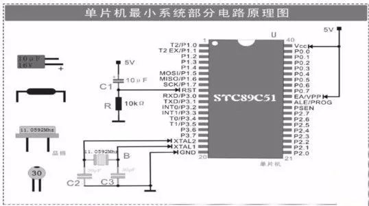
It mainly consists of power supply , reset, oscillation circuit and expansion part. The minimum system schematic is shown in the figure.
Power module
For a complete electronic design , the first problem is to provide power supply modules for the entire system. The stability and reliability of the power modules is the premise and basis for the smooth operation of the system. Although the 51 single-chip microcomputer has the earliest use time and the widest application range, in the actual use process, one typical problem is that compared with other series of single-chip microcomputers , the 51 single-chip microcomputer is more susceptible to interference and the program runs away, overcoming this phenomenon. An important means of emergence is to configure a stable and reliable power supply module for the microcontroller system.
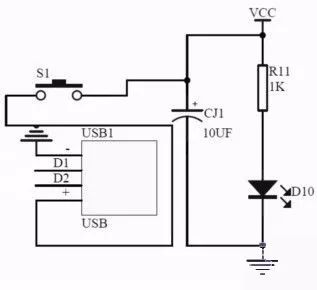
Power module circuit diagram
The power supply of the power supply module in this minimum system can be supplied through the USB port of the computer or by an external stable 5V power supply module. The power indicator LED is connected to the power circuit, and R11 is the current limiting resistor of the LED. S1 is the power switch.
Reset circuit
The setting and resetting of the MCU are all for initializing the circuit to a certain state. Generally speaking, the function of the MCU reset circuit is to initialize a state machine to an empty state, for example, while the MCU is resetting the MCU. The register and the storage device are loaded with a value preset by the manufacturer.
The principle of the reset circuit of the single-chip microcomputer is to externally connect the resistor and the capacitor on the reset pin RST of the single-chip microcomputer to realize the power-on reset. The reset is active when the reset level continues for more than two machine cycles. The duration of the reset level must be greater than the two machine cycles of the microcontroller. The specific value can be calculated by the RC circuit.
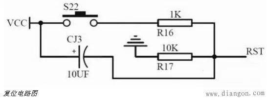
The reset circuit consists of two parts: button reset and power-on reset.
(1) Power-on reset: STC89 series monolithic and high-level reset, usually connect a capacitor to VCC on reset pin RST, and then connect a resistor to GND, thus forming a RC charge and discharge loop to ensure that the microcontroller is on When there is enough time on the RST pin to reset, and then return to the low level to enter the normal working state, the typical values ​​of this resistor and capacitor are 10K and 10uF.
(2) Key reset: The key reset is a switch connected in parallel with the reset capacitor. When the switch is pressed, the capacitor is discharged, RST is also pulled to the high level, and due to the charging of the capacitor, it will remain high for a period of time. Reset the microcontroller.
Oscillation circuit
There is a crystal oscillator in the single-chip system. In the single-chip system, the crystal oscillator is very large. The whole process is called crystal oscillator . He combines the internal circuit of the single-chip microcomputer to generate the clock frequency required by the single-chip microcomputer. The higher the clock frequency provided by the single-chip crystal oscillator, the higher the running speed of the single-chip microcomputer. Fast, single-chip execution of all instructions is based on the clock frequency provided by the microcontroller crystal.
Under normal operating conditions, the average crystal frequency is absolutely accurate to 50 parts per million. Advanced precision is higher. Some crystal oscillators can also be adjusted by a applied voltage within a certain range, called a voltage controlled oscillator (VCO). The crystal oscillator operates in a resonant state with a crystal that converts electrical energy and mechanical energy into each other to provide stable, accurate single-frequency oscillation.
The role of the microcontroller crystal oscillator is to provide the basic clock signal for the system. Usually a system shares a crystal to keep the parts in sync. Some communication systems use different crystals for the fundamental and RF frequencies , and are synchronized by electronically adjusting the frequency.
The crystal is typically used in conjunction with a phase-locked loop circuit to provide the clock frequency required by the system. If different subsystems require clock signals of different frequencies, they can be provided by different phase-locked loops connected to the same crystal.
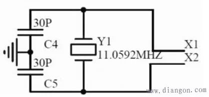
The STC89C51 uses a crystal oscillator of 11.0592MHz as the oscillation source. Since the internal circuit of the microcontroller has an oscillating circuit, it is only necessary to connect a crystal oscillator and two capacitors externally. The capacitance is generally between 15pF and 50pF.
Our company specializes in the production and sales of all kinds of terminals, copper terminals, nose wire ears, cold pressed terminals, copper joints, but also according to customer requirements for customization and production, our raw materials are produced and sold by ourselves, we have their own raw materials processing plant, high purity T2 copper, quality and quantity, come to me to order it!
Cable Terminals
Taixing Longyi Terminals Co.,Ltd. , https://www.lycopperterminals.com